|
INSECTRONICS ROBOT HEXAPOD - ANT
|
|
||||||||||||||||||||||||||||||||||||||||||||||||||||||||||||||||||||||||||||
|
SECTASAURUS - New for 2016, Jameson Hunter is now developing the giant (bulldog) ant based special effects animatronic for this potential cult sc-fi story. Bluebird Marine Systems have been asked to look at re-making the mechanics that went missing many years ago. The object is to produce a few publicity articles and maybe give some aspiring film producers a chance to make a pilot, possibly with the help of crowd funding.
Back in 1982, an English inventor was working on a robot inspired from the form of an ant. He'd been studying ants for some years, keeping wood ants (formica rufus) in a formicarium in his workshop. Ants are capable of lifting 200 times their body mass, due in part to their exoskeletal structure, where the hard body shell carries the structural loads, rather than an internal skeleton and soft outer body tissue. The body of an insect is made of a natural form of plastic, a derivative of keratin. That also means that as an engineering form, the ant design is pure genius molded from millions of years of evolution.
Insects and Arachnids are armed some incredible weapons, that make mammals look positively backward. Even reptiles have piercing fangs and a poison bite. We only have deadly wits. Okay, we don't need to stun our prey so our children have a ready food supply. But the taxman can sting just as hard with a piece of paper and suck the life out of us. Insects have adapted to just about every niche in their small world, with superbly inventive remedies.
Eventually, a film company took on the inventor's idea, and these are some of the original hand drawings produced in connection with that project, salvaged from the archives. Remember that in those days computers and CAD design was a pipedream unless you were a billionaire:
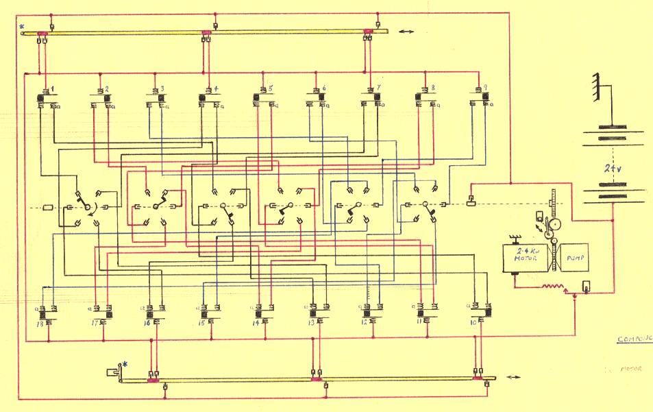
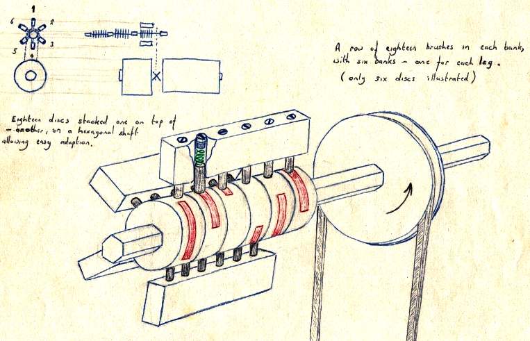
ELECTRICAL CIRCUIT - There are 18 valves for the legs of this robot, each with three positions: Forward, Lock, Back - so, 54 states for each valve to be in. No feedback loops are included in this basic configuration, which should be seen side by side with the hydraulic circuit below.
The circuit diagram above is the electrical switching sequence that energizes 18 solenoid operated three-way hydraulic control valves for a possible 54 valve positions, including the locked positions. The firing order was worked out by studying real ants, and watching their walking movement. Three banks of brushes fed from rotary contacts on a hexagonal shaft. Each bank had a different timing angle that gave 1. Forward and backwards, 2. Left forward and back and 3. Right forward and back. Switching electrically between banks provided directional steering control.
Today, the firing sequence would be digitally programmed and operated by an onboard computer, triggering transistor amplified gate switches. A very realistic walking gait could be achieved as exemplified by the Youtube videos of robots using electric-motor servos at the foot of this page. An interesting mechanical chain/crank drive version from Spain is also shown, which although extremely simple in design, appears to walk reasonably well.
The relative simplicity of this design is a key factor. Changing from a hexagonal shaft to a decagonal shaft would increase variations. But, changing to software triggered valves with feedback from the limb concerned, to include ground contact, temperature, humidity, etc, could mimic a life form and safeguard the robot from getting a leg trapped in soft mud, etc.
The illustration above shows the brush holders, rotary contacts and hexagonal shaft drive of a pre-digital-age mechanical system, where the hexagonal shaft is live and the rotary contacts are slotted onto the shaft into the desired position according to the sequence you want. When you have an idea, draw it. Get it down on paper, or you will forget it. The timing is not unlike that in older cars for the distributor of the ignition system. Early washing machines also had rotary timing switches in stacks for the wash and rinse cycles - now digital programs. The left and right legs can be treated as left and right tracks as if it were a tracked vehicle (tank), for simplification.
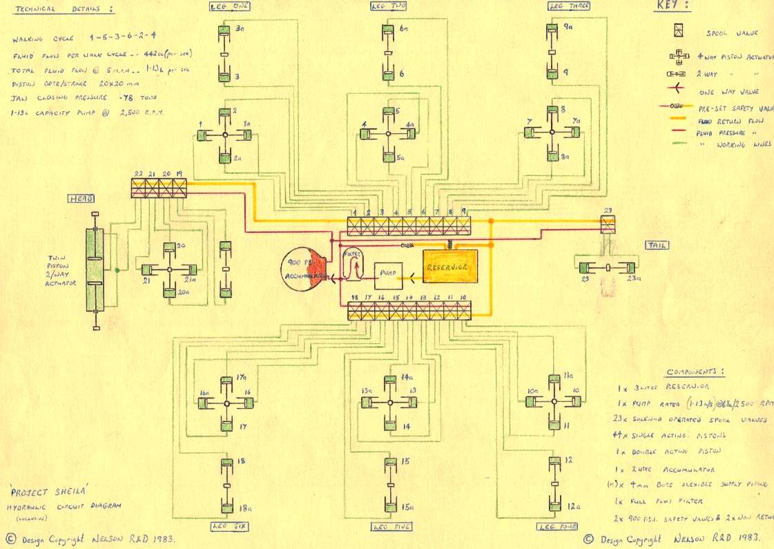
HYDRAULIC CIRCUIT - There are 18 valves shown in the center of this diagram and 36 pistons to operate the legs of this robot. The head and tail pistons are also shown with 5 more 0.25" spool valves. The above diagram should be seen side by side with the electrical circuit above.
The hydraulic circuit diagram above shows the head, leg and tail rams. The solenoid operated valves for the legs are arranged on the body main frame in two banks, with an oil reservoir, pump and pressure vessel. The walking cycle leg activation order is: 1-5-3-6-2-4. This sequence equals one x walk cycle.
PUMP CAPACITY CALCULATIONS WALKING & RUNNING SPEEDS
Taking the forward movement of the robot as 36" (3.0 feet) per walk cycle, we can say that one revolution per second will be 2.0 miles per hour, where 1 mph conveniently = 1.466 ft/sec (17.59"). We won't worry about absolute accuracy here. We just need to have a ball park overview to get a handle on what is possible when designing conceptually.
The hydraulic fluid flow per walk cycle works out to 452 centiliters per second, which equates to 1.357 liters per second @ 6 miles per hour, 4.071 l/s @ 18mph and so on. The leg pistons as shown in the diagrams on this page have a bore and stroke of 20 millimeters = 12.568cc. There are 36 pistons. So one walk cycle = 12.568cc x 36 = .452 liters. With this timing system, the walking speed of the robot is governed by varying the motor revolutions. If using a computer to time the valves, more versatility/agility is built in.
Plan and side views of a 10kW (13.4hp) 60v dc Lynch motor, mated to a hydraulic high pressure vane pump (from auto power steering). This setup is more than capable of powering our robot soldier ant to very high speeds, without straining the motor. Faster in fact than a human can run flat out. You'd have to go some to match a Cheetah = 16 liters a second.
BODYWORK - Click on the picture above to see how to make giant insect body parts quickly and cheaply. This is an educational tutorial for anyone interested in making animatronic displays.
To make this robot effective when engaging humans, a 21 mph running speed would require a fluid flow rate of 4.746 liters per second. Look out Usain Bolt. This figure is attainable, which in turn would need a powerful electric motor coupled to a power steering vane type pump, or a similar high pressure vane pump to those used on fishing vessels for hauling in the nets.
JAWS OPERATION
The jaw closing pressure was calculated as 0.78 tons and .42 seconds from full open to full closed. This of course can be changed with the area of the pistons and available volume from the pressure accumulator chamber, which could see 2 or more tons pressure in less time, if that was a priority. It wasn't. More likely, the military would prefer guns, the police, stun weapons and civilian operators (if any), surveying equipment.
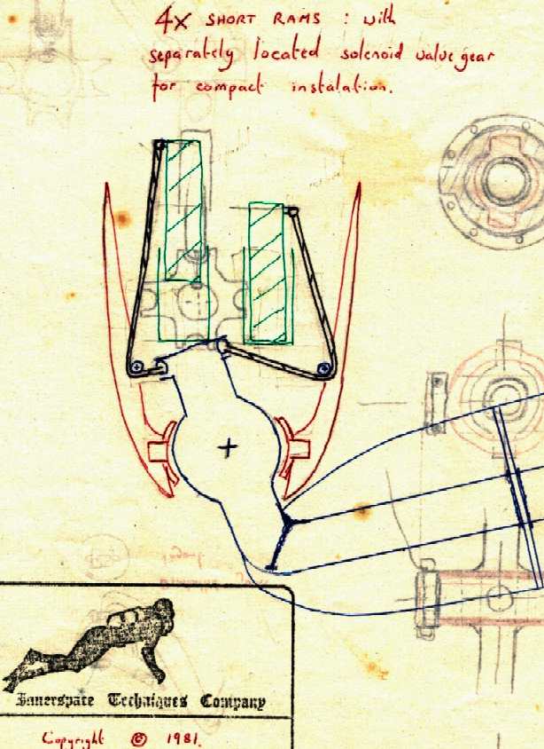
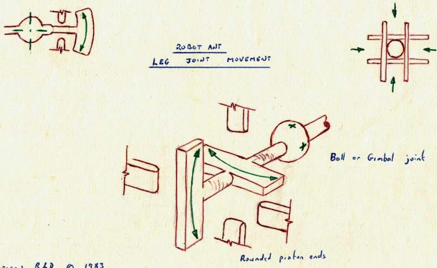
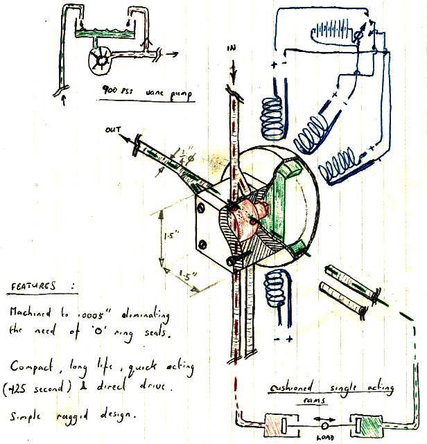
Above, conceptualizing a design by drawing the workings. Two proposals for a ball joint with 4 hydraulic rams placed vertically, operating via cables, and ball joint with swash plates. In the end the version below seemed more practical - a natural development - but you have to start somewhere. The inventive step here was the gimbal to replace the vagaries of a ball joint, which is also free to rotate. Sometimes of course, rotation is a desirable feature - as in our hips and neck joints.
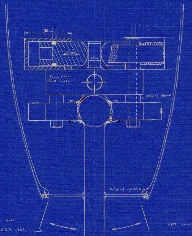
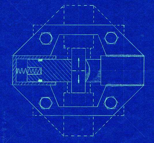
Blueprints for the (final) compact gimbal based "unit" joint, suitable for the legs and head of this particular robot and many other applications when used in conjunction with the tri-function spool valves. In any production version, positional feedback should be included.
The main leg joint (shown above) is a clever hydraulic piston cluster above and below a gimbal type central swivel joint. The single acting pistons work against each other, pushing flat machined swash plates that are oil lubricated. Single acting pistons are more reliable that dual acting rams, because there is no shaft seal, only a piston seal. This arrangement relies on precision control via a two-way hydraulic valve, which must be balanced and capable of dealing with the high flow rates that running will require.
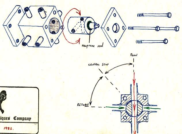
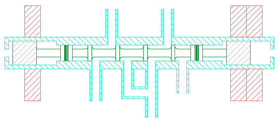
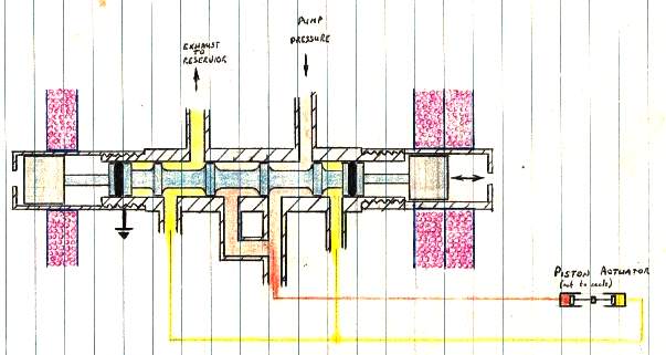
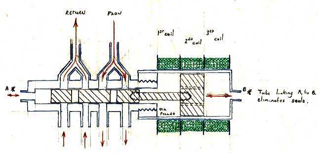
In order to work correctly, the inventor considered the merits of several types of hydraulic control valves - as seen below. It was imperative that the valve could be set in a position to lock a piston, so freezing the movement of the robot, rather than see a gradual collapse. For this reason, three solenoid windings are needed. Once again, in the digital age, programming would take care of this, reducing production costs considerably. The point here though is that this system was designed between 1980 and 1984 to give a robot capable of lifting humans, or giving them rides, etc. The real thing. One can imagine the uses for such a robot in combat. Armour it and give it a weapon with laser ranging, and you'd have a fearless, disposable infantryman. Food for thought and surprising really, that we don't have mechanical soldiers like this today for hostile regions like Afghanistan.
The rotary valve design and rotary solenoid, a bit like a stepper motor, with exploded view and assembled cutaway view. The rotary magnetic operation may provide more torque than the spool version below. - but the spool version (below) is shown on the CAD robot drawing above. Note the design to minimise fluid drag, so heat build up.
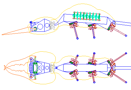
Two linear valve designs, spool and flat bar gate (above and below). Interesting how seals could be eliminated. The 1/4" spool version on this drawing from 1983 is seen in the CAD drawings above, nine units per side of the main frame. Three solenoid windings provide pressure/lock/release flow positions - essential for complex movements and economical operation.
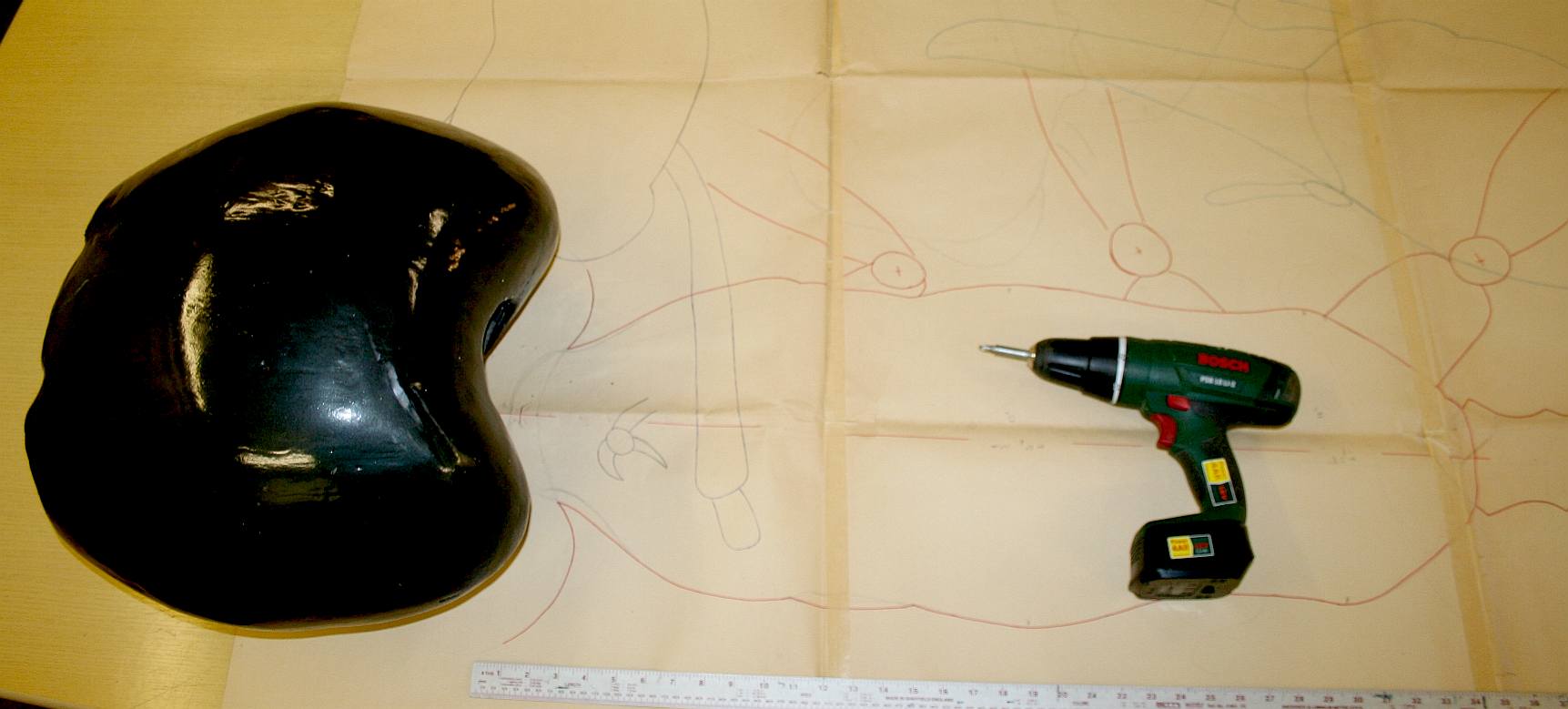
We are unable to publish any of the original working drawings because the paper they are drawn on full size (called lofting) is something like 10 x 10 feet. But we now have CAD and have input some information to share with you, in the drawings published, so that students of robot design can appreciate the chassis configuration and design practicalities which is very much the same for a robot ant as for a robot human, save the balance issue, which is easily solved with an appropriate sensing arrangement and balance control feedback loops.
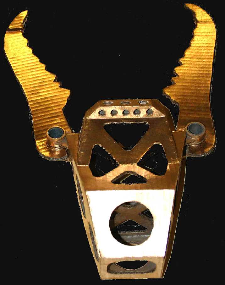
A light projector was used to obtain superbly accurate dimensions from a specimen Bulldog Ant - see below. This system is suitable for application to any insect.
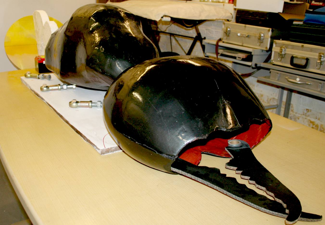
It is a pity that the design is not exoskeletal (monocoque). We imagine that this would be extremely complex design wise, but much simpler for the construction.
With a design like this, mated to computer controls, any autonomous variant will be a truly awesome machine with limitless possibilities.
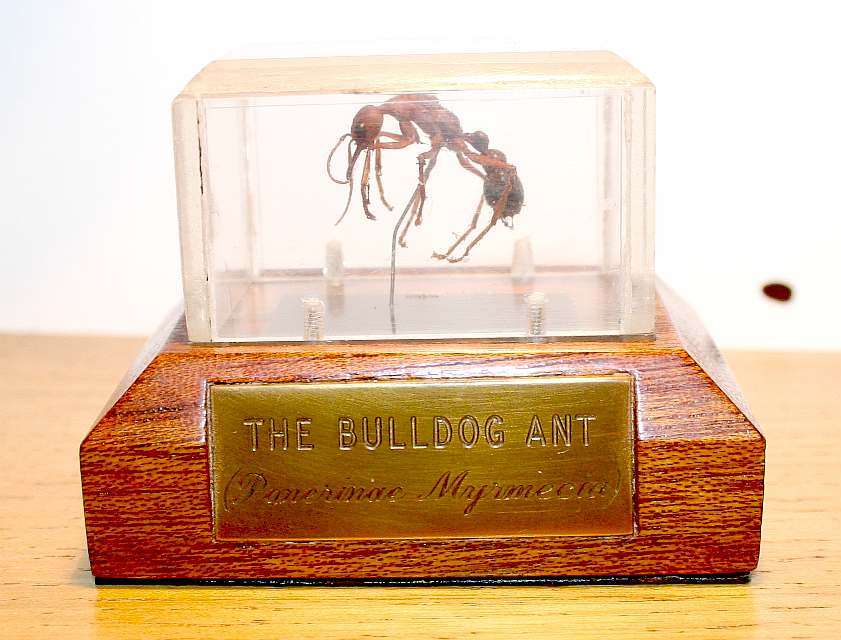
This was the specimen that changed the look and size of the robot ant development. The bulldog ant from Australia is a particularly interesting animal. It can be a solitary hunter. It can paralyze a human and it has stereoscopic vision. Click on the picture to see more about the making of the protective showcase.
NOVEMBER 2015 - The above artwork is with Bluebird Marine Systems, who are now looking to make the missing parts and re-assemble the giant animatronic ant for Jameson Hunter Ltd. Does that mean we might see a script of film anytime soon?.
GIANT INSECT DESIGN and PRODUCTION SERVICE
Should film or special effects companies, natural history museums or other events organisations be interested in such a service, to include production of the artwork to a scale of your choosing, please contact us and we will put you in touch with an engineering and molding team who can provide a quote for you.
NOTE: These copyright designs are now the intellectual property of Blueplanet Universal Holdings Ltd, to be used for publicity (marketing) and special effects for the British science fiction film called Sectasaur.
OTHER ROBOT ANT PROJECTS
This subject has received a lot of attention from other engineers:-
A-Pod is an ant inspired hexapod robot with a 2 DOF abdomen (tail), a 3 DOF head with large mandibles. 6 legs with 3 DOF each. Total 25 servos. This video demonstrates body movement and mandible control.
The designer still has to make some mechanical improvements to the legs
(explaining the small amount of walking). The robot is remotely controlled with a custom 2,4 GHz RC transmitter. The Basic Atom Pro 28
is/are used as the main micro-controller(s).
FireAnt is based on Zenta's A-POD and made from all aluminum anodized brackets. The kit includes the new digital HV220 robotic servos with position and force feedback. This gives FireAnt life like movement and the ability to sense its environment. It can sense the force the pincher's are applying with no additional sensors. It can also feel when a leg is touching something in both down and forward directions for autonomous terrain adaptation.
http://www.orionrobotics.com/FireAnt-Hexapod-Robot_p_248.html
BBC NEWS 29 MARCH 2013 - SUPER ORGANISMS
There are an estimated 20,000 species of ants in the world. Ant colonies have structured social system, with different castes - worker, soldier, queen and drone - all of which carry out specific tasks for the colony. Ant colonies are sometimes referred to as "superorganisms" because they appear to operate as a single entity.
Scientists in the
US have built and tested robotic ants that they say behave just like a real ant colony.
The robots do not resemble their insect counterparts; they are tiny cubes equipped with two watch motors to power the wheels that enable them to move.
But their collective behaviour is remarkably ant-like.
There are many other research and engineering projects that take inspiration from nature to solve problems or design robots, as Dr Paul Graham, a biologist from the
University of Sussex, explained.
"The classic example," he said, "is the way in which we design information networks to move packets of data around.
"Ants don't have someone in charge telling them where to go, so you can [mimic this].
Dr
Graham Biography: During a Psychology degree I became interested in Artificial
Intelligence, specifically the prospect of capturing aspects of biological
intelligence by mimicking insects. This led to a PhD at Sussex with Prof Tom Collett, where we have studied spatial cognition in ants. Following my DPhil I completed BBSRC, Leverhulme and RCUK postdocs before becoming a Reader in 2012.
My major research involves studies of how insects navigate around their environment. Insects are capable of amazing feats of navigation, even though they have limited neural resources. Understanding how these small creatures navigate will help us better understand how the behaviour and cognition of an animal is constrained by the environment within which it operates. I am also interested in the application of insect research for the development of
autonomous
robots.
http://www.sussex.ac.uk/profiles/dr_paul_graham http://www.bbc.co.uk/news/ants http://fallout.wikia.com/wiki/File:Giant_ant http://killallmonsters.com/ants http://themediumandthemayhem.net/2011/08/26/ferroluar/ http://fallout.wikia.com/wiki/Giant_ant
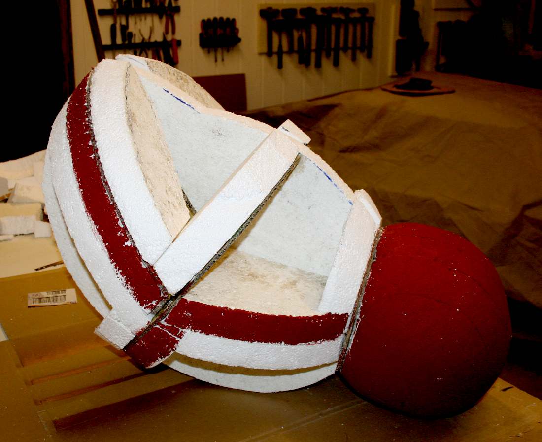
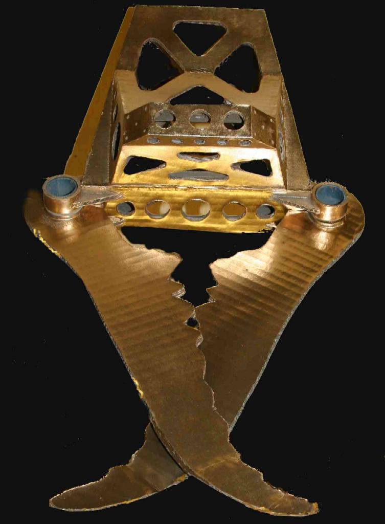
Theory put into practice. Shown above is the template for the head of this robot insect, which you can see in the CAD drawing above (in blue) and note the gimbal 4-way piston joint which bolts to the back-plate. The inventor nearly always builds a model (even if full size in this case) to be sure of his calculations.
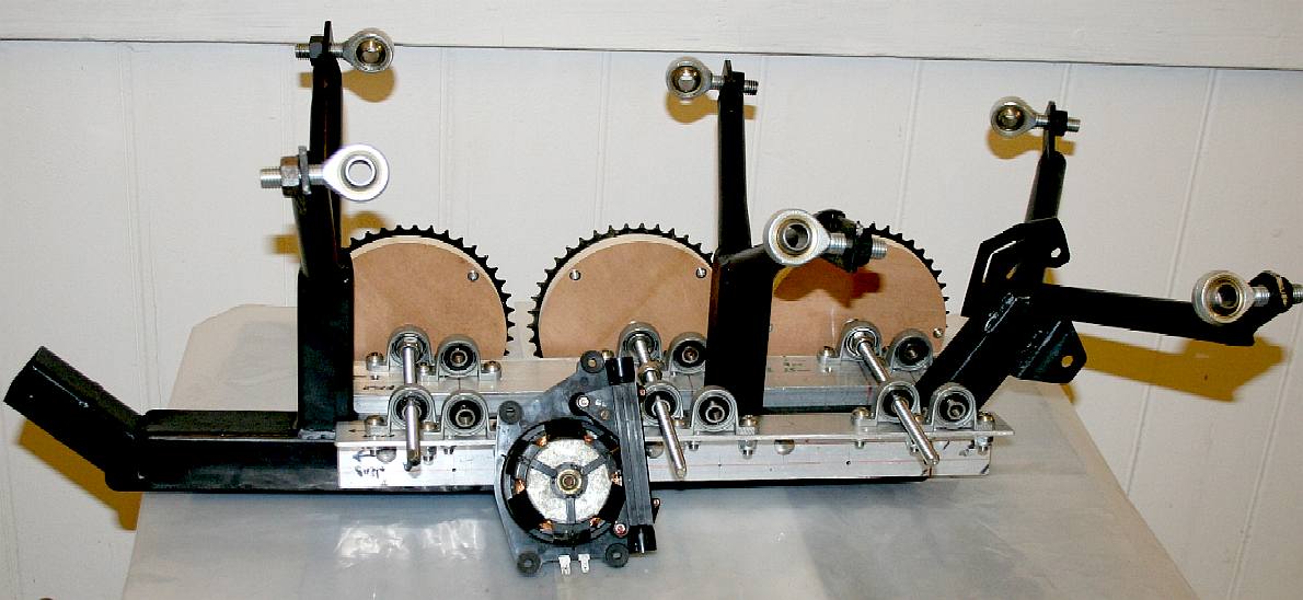
DINOBOT - Steel frame of the new robot design. This is a simplified mechanical transmission using chains and sprockets to reduce cost and improve operational reliability.
ANTICS - ARDUINO - ARMOUR - ARTWORK - BLACK BOX - CHAT GPT - ELECTRONICS - ENERGY - FRAME - FORMICARIUM HEAD - INVISIBILITY - JAWS - KITS - LEGS - MECHANICS - MOTORS - MOVIE - RASPBERRY Pi - R/C DRONE - SENTRY - SOFTWARE SIM CARDS - SMARTPOHNES - SOUND PROOFING - SPACE ROVERS - SPEED - SUSPENSION - TAIL - WEAPONS - WARGAMING
DINOSAURS - DOLPHINS - HUMANOIDS - RAYS - SHARKS - WHALES
Lurking beneath the Antarctic ice is a discovery that scientist will die for.
BIPEDS | CYBEE | HEXAPODS | HUMANOIDS | MANTIS | OCTOPODS QUADRUPEDS | ROBOBEE | ROBOT ANT | SPIDERBOT | STOMPY | TRIPODS
|
|||||||||||||||||||||||||||||||||||||||||||||||||||||||||||||||||||||||||||||
|
This website is copyright © 1991- 2023 Electrick Publications. All rights reserved. The bird logo and names Solar Navigator and Blueplanet Ecostar are trademarks ™. The Blueplanet vehicle configuration is registered ®. All other trademarks hereby acknowledged and please note that this project should not be confused with the Australian: 'World Solar Challenge'™which is a superb road vehicle endurance race from Darwin to Adelaide. Max Energy Limited is an educational charity working hard to promote world peace.
|
|||||||||||||||||||||||||||||||||||||||||||||||||||||||||||||||||||||||||||||
