|
TRACKING THE SUN FOR MAX ENERGY
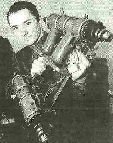
Alex Martin (Al's Robotics)
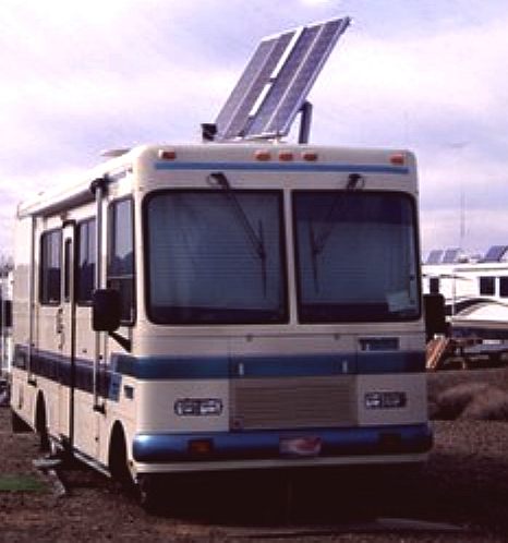
In order to keep SolarNavigator's
solar panels looking at the sun (as much as
possible) it is considered necessary to design the panels to be
movable in at least one plane. Two planes would be better, but
this has proved to be impractical to date. However, experimentation
continues apace.
The
well known local robot designer, Alex
Martin, joined the team of experts now
supporting the project specifically to design and construct a suitable
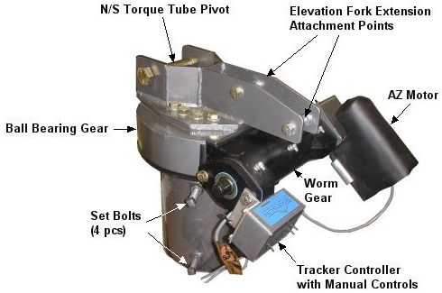
system for Solar Navigator. The 'Tracker' has to be rugged and
reliable, able to withstand all the high seas can throw at it. The
sensing head will not only control an electro mechanical
actuator, but
will also show the crew (if present) where the sun is shining. This may assist
in fine tuning future routes in the long term. The
diagram below illustrates how the moveable wings can be angled to face
the sun at 90 degrees. In
addition to tilt-wings for panel orientation, electronic solar tracking
circuits will be used, commonly known as MMPTs. These devices will be
all the more useful with roughly half the panel area receiving solar
energy at a reduced (static) rate and the other half at the fuller
(tilting) rate.
COMPONENTS
FOR WING TILT:
Light
sensor: LDR
Sensor
processor: microchip PIC comparator
Maths
processor: microchip PIC
Serial
port override: handheld device or laptop
Actuator
drive: independently controlled by microchip PIC
Actuator
feedback sensor: processed by microchip PIC
ELECTRONIC
MAXIMUM POWER POINT TRACKER
The
PlanetSolar boat was said to use MPPT (Maximum Power Point Tracker) and
tilt orientation of the panels, but it is unclear if panel tilt was used
anywhere but the rear panel. MMPT is the electronics between solar panels and the battery.
Most solar cars in the Darwin to Adelaide race use such a system. Maximum power point tracking
(MPPT) is a technique that grid-tie inverters, solar battery chargers and similar devices use to get the maximum possible power from one or more photovoltaic devices, typically solar panels, though optical power transmission systems can benefit from similar technology.
Solar cells have a complex relationship between solar irradiation, temperature and total resistance that produces a non-linear output efficiency known as the I-V curve. It is the purpose of the MPPT system to sample the output of the cells and apply the proper resistance (load) to obtain maximum power for any given environmental conditions. MPPT devices are typically integrated into an electric power converter system that provides voltage or current conversion, filtering, and regulation for driving various loads, including power grids,
batteries, or motors. 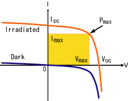
Current-voltage characteristics of a solar cell at a particular light level, and in darkness. The area of the yellow rectangle gives the output power. Pmax denotes the maximum power point I-V
CURVE
Photovoltaic cells have a complex relationship between their operating environment and the maximum power they can produce. The fill factor, abbreviated FF, is a parameter which characterizes the non-linear electrical behavior of the solar cell. Fill factor is defined as the ratio of the maximum power from the solar cell to the product of Open Circuit Voltage Voc and Short-Circuit Current Isc. In tabulated data it is often used to estimate the maximum power that a cell can provide with an optimal load under given conditions, P=FF*Voc*Isc. For most purposes, FF, Voc, and Isc are enough information to give a useful approximate model of the electrical behavior of a photovoltaic cell under typical conditions.
For any given set of operational conditions, cells have a single operating point where the values of the current (I) and Voltage (V) of the cell result in a maximum power output. These values correspond to a particular load resistance, which is equal to V / I as specified by Ohm's Law. The power P is given by P=V*I. A photovoltaic cell, for the majority of its useful curve, acts as a constant current source. However, at a photovoltaic cell's MPP region, its curve has an approximately inverse exponential relationship between current and voltage. From basic circuit theory, the power delivered from or to a device is optimized where the derivative (graphically, the slope) dI/dV of the I-V curve is equal and opposite the I/V ratio (where dP/dV=0). This is known as the maximum power point (MPP) and corresponds to the "knee" of the curve.
A load with resistance R=V/I equal to the reciprocal of this value draws the maximum power from the device. This is sometimes called the characteristic resistance of the
cell. This is a dynamic quantity which changes depending on the level of illumination, as well as other factors such as temperature and the age of the cell. If the resistance is lower or higher than this value, the power drawn will be less than the maximum available, and thus the cell will not be used as efficiently as it could be. Maximum power point trackers utilize different types of control circuit or logic to search for this point and thus to allow the converter circuit to extract the maximum power available from a cell.
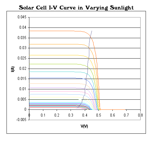
Solar cell I-V curves where a line intersects the knee of the curves where the maximum power point is located.
CLASSIFICATION
Controllers usually follow one of three types of strategies to optimize the power output of an array. Maximum power point trackers may implement different algorithms and switch between them based on the operating conditions of the array.
PETERB AND OBSERVE
In one method, the controller adjusts the voltage by a small amount from the array and measures power; if the power increases, further adjustments in that direction are tried until power no longer increases. This is called the perturb and observe method and is most common, although this method can result in oscillations of power output. It is referred to as a hill climbing method, because it depends on the rise of the curve of power against voltage below the maximum power point, and the fall above that point. Perturb and observe is the most commonly used MPPT method due to its ease of implementation. Perturb and observe method may result in top-level efficiency, provided that a proper predictive and adaptive hill climbing strategy is adopted.
INCREMENTAL
CONDUCTANCE
In the incremental conductance method, the controller measures incremental changes in array current and voltage to predict the effect of a voltage change. This method requires more computation in the controller, but can track changing conditions more rapidly than the perturb and observe method (P&O). Like the P&O algorithm, it can produce oscillations in power output. This method utilizes the incremental conductance (dI/dV) of the photovoltaic array to compute the sign of the change in power with respect to voltage (dP/dV).
The incremental conductance method computes the maximum power point by comparison of the incremental conductance (ΔI/ΔV) to the array conductance (I/V). When these two are the same (I/V=ΔI/ΔV), the output voltage is the MPP voltage. The controller maintains this voltage until the irradiation changes and the process is repeated.
CURRENT SWEEP METHOD
The current sweep method uses a sweep waveform for the PV array current such that the I-V characteristic of the PV array is obtained and updated at fixed time intervals. The maximum power point voltage can then be computed from the characteristic curve at the same intervals.

CONSTANT VOLTAGE
The term "constant voltage" in MPP tracking is used to describe different techniques by different authors, one in which the output voltage is regulated to a constant value under all conditions and one in which the output voltage is regulated based on a constant ratio to the measured open circuit voltage (VOC). The latter technique is referred to in contrast as the "open voltage" method by some authors. If the output voltage is held constant, there is no attempt to track the maximum power point, so it is not a maximum power point tracking technique in a strict sense, though it does have some advantages in cases when the MPP tracking tends to fail, and thus it is sometimes used to supplement an MPPT method in those cases.
In the "constant voltage" MPPT method (also known as the "open voltage method"), the power delivered to the load is momentarily interrupted and the open-circuit voltage with zero current is measured. The controller then resumes operation with the voltage controlled at a fixed ratio, such as 0.76, of the open-circuit voltage VOC. This is usually a value which has been determined to be the maximum power point, either empirically or based on modeling, for expected operating conditions. The operating point of the PV array is thus kept near the MPP by regulating the array voltage and matching it to the fixed reference voltage Vref=kVOC. The value of Vref may be also chosen to give optimal performance relative to other factors as well as the MPP, but the central idea in this technique is that Vref is determined as a ratio to VOC.
One of the inherent approximations to the "constant voltage" ratio method is that the ratio of the MPP voltage to VOC is only approximately constant, so it leaves room for further possible optimization.
COMPARISON OF METHODS
Both perturb and observe, and incremental conductance, are examples of "hill climbing" methods that can find the local maximum of the power curve for the operating condition of the array, and so provide a true maximum power point.
The perturb and observe method can produce oscillations of power output around the maximum power point even under steady state illumination.
The incremental conductance method has the advantage over the perturb and observe method that it can determine the maximum power point without oscillating around this value. It can perform maximum
power point tracking under rapidly varying irradiation conditions with higher accuracy than the perturb and observe method. However, the incremental conductance method can produce oscillations and can perform erratically under rapidly changing
atmospheric conditions. The computational time is increased due to slowing down of the sampling frequency resulting from the higher complexity of the algorithm compared to the P&O method.
In the constant voltage ratio (or "open voltage") method, the current from the photovoltaic array must be set to zero momentarily to measure the open circuit voltage and then afterwards set to a predetermined percentage of the measured voltage, usually around 76%. Energy may be wasted during the time the current is set to zero. The approximation of 76% as the MPP/VOC ratio is not necessarily accurate though. Although simple and low-cost to implement, the interruptions reduce array efficiency and do not ensure finding the actual maximum power point.
MPPT PLACEMENT
Traditional solar inverters perform MPPT for an entire array as a whole. In such systems the same current, dictated by the inverter, flows through all panels in the string. Because different panels have different IV curves and different MPPs (due to manufacturing tolerance, partial shading, etc.) this architecture means some panels will be performing below their MPP, resulting in the loss of energy.
Some companies (see power optimizer) are now placing peak power point converters into individual panels, allowing each to operate at peak efficiency despite uneven shading, soiling or electrical mismatch.
OPERATION WITH BATTERIES
At night, an off-grid PV power system may use batteries to supply loads. Although the fully charged battery pack voltage may be close to the PV array's maximum power point voltage, this is unlikely to be true at sunrise when the battery has been partially discharged. Charging may begin at a voltage considerably below the array maximum power point voltage, and an MPPT can resolve this mismatch.
When the batteries in an off-grid system are fully charged and PV production exceeds local loads, an MPPT can no longer operate the array at its maximum power point as the excess power has no load to absorb it. The MPPT must then shift the array operating point away from the peak power point until production exactly matches demand. (An alternative approach commonly used in spacecraft is to divert surplus PV power into a resistive load, allowing the array to operate continuously at its peak power point.)
In a grid-tied photovoltaic system, the grid must be forced to absorb all excess power delivered from solar panels. The MPPT in a grid tied PV system will always attempt to operate the array at its maximum power point. 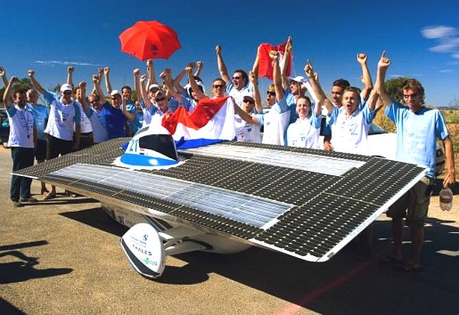
LINKS
http://www.timnolan.com/index.php?page=arduino-ppt-solar-charger
Home-page
Robots
Tutorials
Links
E-mail
Circuits
Events
BEAM
PIC-Microchip
Shop
Computers
FMM-RobotWars
Sponsors
Suggested-reading
Ebay-Listings
Serial-Speed-Controllers
MicroMouse
Walkers
Driller-Killer Laptops
Excaliber-Robot
Retox-Drill-Robot
Robot-motors
SOLAR
TRACKING THEORY & PRACTICAL EXAMPLES
SOLAR
WING PANEL ACTUATORS & CONTROL KITS
ELECTRONIC
COMPUTER CHIP SUN TRACKING SOLUTION
MPPT
ELECTRONIC SUN TRACKER PCB DEVELOPMENT
The
ultimate Robot Boat. Solarnavigator uses an advanced SWASSH
hull as the platform
to
mount the world's first autonomous circumnavigation. A successful
expedition could pave the way for improved safety
at sea.
|