|
HELICOPTERS
|
||
|
A helicopter is an aircraft which is lifted and propelled by one or more horizontal rotors consisting of two or more rotor blades. Helicopters are classified as rotorcraft to distinguish them from fixed-wing aircraft because the helicopter derives its source of lift from the rotor blades rotating around a mast. In fact, the word 'helicopter' originates from the Greek words elikoeioas (helical or spiral) and pteron (wing or feather).
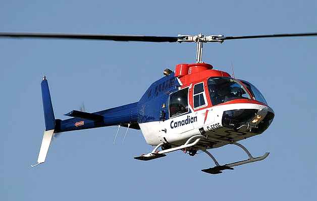
Canadian Bell 206 helicopter
The primary advantages of the helicopter are due to its rotor, which provides lift in a vertical direction, giving it the ability to take off and land vertically and to maintain a steady hover in the air over a single point on the ground. This allows the helicopter to land and take off from pinnacles and confined areas that airplanes are not able to take off from, including heliports in the middle of busy cities and rugged terrain in remote areas. The helicopter is used for rescue, medical evacuation and as an observation platform. Other operations that involve the use of helicopters are fire fighting, tours, as an aerial crane, logging, personnel transport, electronic news gathering, law enforcement, military and for pleasure.
Although helicopters were developed and built during the first half century of flight, some even reaching limited production, it wasn't until 1942 that a helicopter designed by Igor Sikorsky became the first helicopter to enter full-scale production, totalling over 400 copies. Even though most previous designs utilized more than one main rotor, it was the single main rotor with antitorque tail rotor configuration of this design that would come to be recognized worldwide as the helicopter.
History
Since 400 BC, the Chinese had a bamboo flying top that was used as a children's toy. Eventually, this flying top toy made it to Europe and is depicted in a 1463 European painting. Pao Phu Tau (抱朴子) was a 4th-century book in China describing some of the ideas inherent to rotary wing aircraft. Around 1490, Leonardo da Vinci first conceived a semi-practical machine, named in his "Codice Atlántico", that could be described as an "aerial screw".
The word "helicopter" (hélicoptère) was coined in 1861 by Gustave de Ponton d'Amécourt, a French inventor who demonstrated a small steam-powered model. Ján Bahýľ, a Slovak inventor, developed a helicopter model powered by an internal combustion engine that in 1901 reached a height of 0.5 meters. On May 5, 1905 his helicopter reached 4 meters in altitude and flew for over 1500 meters.
In 1906, two brothers, Jacques and Louis Breguet, began experimenting with airfoils for helicopters and in 1907, those experiments resulted in the Gyroplane No.1. Although there is some discrepancy about the dates, sometime between 14 August and 29 September 1907, the Gyroplane No. 1 lifted its pilot up into the air about two feet (0.6 meters) for a minute. However, the Gyroplane No. 1 proved to be extremely unsteady and required a man at each corner of the airframe to hold it steady. For this reason, the flights of the Gyroplane No. 1 are considered to be the first manned flight of a helicopter, but not a free or untethered flight. That same year, fellow French inventor Paul Cornu designed and built a helicopter that used two 20-foot (6-meter) counter-rotating rotors driven by a 24-hp (18-kW) Antoinette engine. On November 13, 1907, it lifted its inventor to 1 foot (0.3 meters) and remained aloft for 20 seconds. Although this flight was smaller in its achievement than that of the Breguet brothers, it was greater in accomplishment being that it was the first true free flight with a pilot. The Cornu helicopter would achieve a height of nearly 2 meters but also proved to be unstable and was abandoned after only a few flights.
In the early 1920s, Raul Pateras Pescara de Castelluccio, an Argentinian working in Europe, demonstrated one of the first successful applications of cyclic pitch. His coaxial, contra-rotating, biplane rotors were able to be warped to cyclically increase and decrease the lift they produced; and the rotor hub could also tilt, both allowing the aircraft to move laterally without a separate propeller to push or pull it. Pescara is also credited with demonstrating the principle of autorotation, the method by which helicopters land safely after engine failure. By January 1924, Pescara's helicopter No. 3 was capable of flights up to 10 minutes. One of Pescara's contemporaries, Frenchman Etienne Oemichen, set the first helicopter world record recognized by the Fédération Aéronautique Internationale on 14 April 1924, flying his helicopter 360 meters (1,181 feet). On 18 April 1924, Pescara beat Oemichen's record, flying for a distance of 736m (nearly a half mile) in 4 minutes and 11 seconds (about 8 mph, 13 km/h) maintaining a height of six feet. Not to be outdone, Oemichen reclaimed the world record on 4 May when he flew his No. 2 machine again for a 14-minute flight covering 5,550 feet (1.05 mi, 1.692 km) while climbing to a height of 50 feet (15 meters). Oemichen also set the 1-km closed-circuit record at 7 minutes 40 seconds.
During this time, Juan de la Cierva was developing and introducing the first practical autogyro. In 1923, the rotorcraft that became the basis for the modern helicopter began to take shape, in the form of an autogyro. Cierva discovered aerodynamic and structural deficiencies in his early designs that could cause his autogyros to flip over after takeoff. The flapping hinges Cierva designed allowed the rotor to develop lift equally on the left and right halves of the rotor disk. A crash in 1927 led to the development of the drag hinge. These two developments allowed for a stable rotor system, not only in a hover, but in forward flight.
In 1922, Albert Gillis von Baumhauer, a Dutch aeronautical engineer, started studying VTOL rotor craft. His first prototype 'flew' ('hopped' and hovered really) on September 24, 1925, with Dutch Army-Air arm Captain Floris Albert van Heijst at the controls. The controls that Captain van Heijst used were Von Baumhauer's inventions, the cyclic and collective. Patents were granted Von Baumhauer by the British ministry of aviation on January 31, 1927, under number 265,272.
Soviet aeronautical engineers Boris Yuriev and Alexei Cheremukhin began experiments with the TsAGI 1-EA helicopter in 1931. A single rotor helicopter, with dual forward and aft anti-torque propellers, it reached an altitude of 605 meters (1,984 ft) on August 14, 1932 with Cheremukhin at the controls.
The German Focke-Wulf Fw 61 was the first viable helicopter first flying in 1936. The Fw 61 broke all of the helicopter world records in 1937. Nazi Germany used helicopters in small numbers during World War II. Models such as the Flettner Fl 282 Kolibri synchropter were used in the Mediterranean Sea, while the Focke Achgelis Fa 223 Drache was used in Europe.
Mass production of the military version of the Sikorsky XR-4 began in May 1942 for the United States Army; this was used over Burma for rescue duties. It was also used by the Royal Air Force, the first British military unit to be equipped with helicopters being the Helicopter Training School, formed in January 1945 at RAF Andover with nine Sikorsky R-4B Hoverfly I helicopters.
The Bell 47 designed by Arthur Young became the first helicopter to be licensed (in March 1946) for certified civilian use in the United States. Two decades later the Bell 206 became the most successful commercial helicopter ever built with more hours and more industry records than any other aircraft in the world.
Reliable helicopters capable of stable hover flight were developed decades after fixed-wing aircraft. This is largely due to higher engine power density requirements than fixed-wing aircraft. Improvements in fuels and engines during the first half of the 20th century were a critical factor in helicopter development. The availability of lightweight turboshaft engines in the second half of the 20th century, pioneered by the Kaman K-225 synchropter, [1], which first flew with gas turbine power late in 1951, led to the development of larger, faster, and higher-performance helicopters. Turboshaft engines are the preferred powerplant for all but the smallest and least expensive helicopters today.
Uses of helicopters
Aerial cranes
One of the most unusual commercial uses of helicopters is the aerial crane or skycrane. As aerial cranes, helicopters carry loads connected to long cables or slings in order to place heavy equipment such as transmission towers and large air conditioning units on the tops of tall buildings or when an item must be raised up in a remote area, such as a radio tower raised on the top of a hill or mountain, far from the nearest road.
Helicopters were first used as aerial cranes in the 1950s, but it was not until the 1960s that the popularity of the use of skycranes in the construction and other industries began to catch on. The most popular use of helicopters as aerial cranes is in the logging industry to lift large trees out of rugged terrain where vehicles aren't able to reach, or where environmental concerns prohibit the buildings of roads. These operations are referred to as longline because of the long, single sling line used to carry the load.
Aerial firefighting
Aerial firefighting (or water bombing) is a method to combat wildfires that often uses helicopters. Helicopters may be fitted with tanks or carry buckets or deliver firefighters who rappel to the ground below. Buckets are usually filled by submerging in lakes, rivers, reservoirs, or portable tanks. The most popular of the buckets is the flexible Bambi bucket. Tanks may be filled on the ground or water may be siphoned from lakes or reservoirs through a hanging snorkel. Helicopters are also used to resupply firefighters on the ground with tools, food, water and other supplies. Popular firefighting helicopters include variants of the Bell 204 and the Erickson S-64 Aircrane helitanker. The Erickson helitanker also has a sea snorkel for filling while in flight.
Air ambulance
Helicopters are often used as an air ambulance for emergency medical assistance in situations where either a traditional ambulance cannot easily or quickly reach the scene or when a patient needs to be transported at a distance where air transportation is most practical. Air ambulance crews are supplied with equipment that enables them to provide medical treatment to a critically injured or ill patient. The use of helicopters as an air ambulance is sometimes referred to as MEDEVAC, or patients are referred to as being "airlifted", or "medevaced".
Helicopter configurations
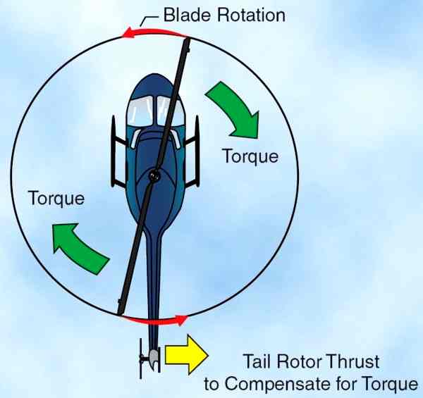
Most helicopters have a single, main rotor but require a separate rotor to overcome torque. This is accomplished through a variable pitch, antitorque rotor or tail rotor. This is the design that Igor Sikorsky settled on for his VS-300 helicopter and it has become the recognized convention for helicopter design, although, designs do vary. When viewed from above, designs from Germany, United Kingdom and the United States are said to rotate counter-clockwise, all others are said to rotate clockwise. This can make it difficult when discussing aerodynamic effects on the main rotor between different designs, since the effects may manifest on opposite sides of each aircraft.
Torque effect on a helicopter
Antitorque
With a single main rotor helicopter, the creation of torque as the engine turns the rotor creates a torque effect which causes the body of the helicopter to turn in the opposite direction of the rotor. To eliminate this effect, some sort of antitorque control must be used, with a sufficient margin of power available to allow the helicopter to maintain its heading and provide yaw control. The three most common controls used today are the traditional tail rotor, Eurocopter's Fenestron™ (also called a fantail), and MD Helicopters' NOTAR®. Tail rotor
The tail rotor is a smaller rotor mounted vertically or near-vertical on the tail of a traditional single-rotor helicopter. The tail rotor either pushes or pulls against the tail to counter the torque. The tail rotor drive system consists of a drive shaft powered from the main transmission and a gearbox mounted at the end of the tail boom. The drive shaft may consist of one long shaft or a series of shorter shafts connected at both ends with flexible couplings. The flexible couplings allow the drive shaft to flex with the tail boom. The gearbox at the end of the tailboom provides an angled drive for the tail rotor and may also include gearing to adjust the output to the optimum RPM for the tail rotor. On some larger helicopters, intermediate gearboxes are used to transition the tail rotor drive shaft from along the tailboom or tailcone to the top of the tail rotor pylon which also serves as a vertical stabilizing airfoil to alleviate the power requirement for the tail rotor in forward flight. It may also serve to provide limited antitorque within certain airspeed ranges in the event that the tail rotor or the tail rotor flight controls fail.
Fenestron
A Fenestron (or Fantail) is a ducted fan mounted on the tail boom of the helicopter and used in place of a tail rotor. Its housing is integral with the tail skin, and while conventional tail rotors typically possess a maximum of 5 rotor blades, Fenestrons have between 8 and 18 blades. These are arranged in varying distance, so that the noise is distributed over different frequencies and thus appears quieter. The housing allows a higher rotational speed than a conventional rotor and therefore it can have a smaller size than a conventional rotor.
The Fenestron tail rotor was used for the first time at the end of the 1960s on the second experimental model of Sud Aviation's SA 340, and on the later model Aérospatiale SA 341 Gazelle. Besides Eurocopter and its predecessors, a ducted fan tail rotor was also used on the canceled military helicopter project, the United States Army's RAH-66 Comanche.
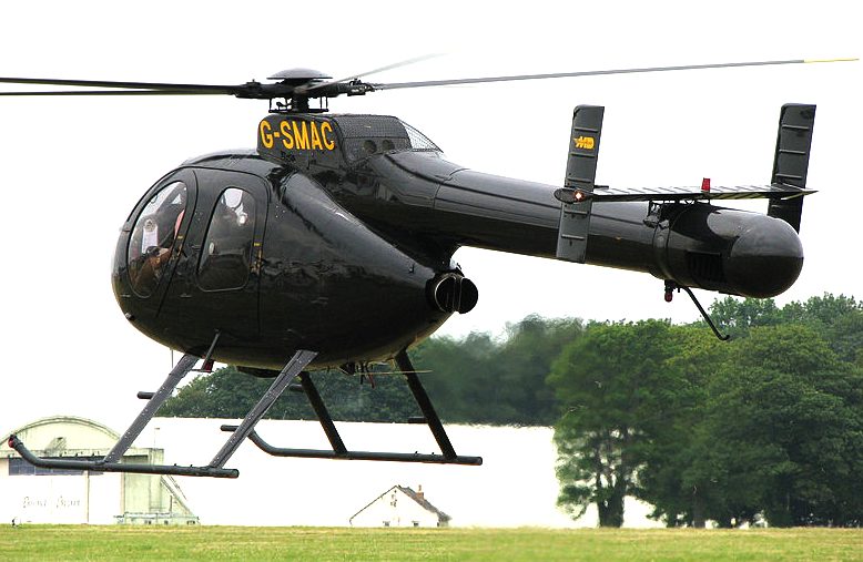
NOTAR
NOTAR, an acronym for NO TAil Rotor, is a relatively new helicopter anti-torque system originally developed by Hughes Helicopters and currently produced by MD Helicopters which eliminates the use of the tail rotor on a helicopter.
Although the concept, which uses the Coandă effect, took some time to refine, the NOTAR system is simple in theory and works to provide antitorque the same way a wing develops lift. A variable pitch fan is enclosed in the aft fuselage section immediately forward of the tail boom and driven by the main rotor transmission.
This fan forces low pressure air through two slots on the right side of the tailboom, causing the downwash from the main rotor to hug the tailboom, producing lift, and thus a measure of antitorque proportional to the amount of airflow from the rotorwash. This is augmented by a direct jet thruster (which also provides directional yaw control) and vertical stabilizers.
Development of the NOTAR system dates back to 1975 when engineers at Hughes Helicopters began concept development work. In December 1981 Hughes flew a OH-6A fitted with NOTAR for the first time. A more heavily modified prototype demonstrator first flew in March 1986 and successfully completed an advanced flight-test program, validating the system for future application in helicopter design.
There are three production helicopters that utilize the NOTAR system, all produced by MD Helicopters:
Dual rotors (contra-rotating)
Contra-rotating rotors, are rotorcraft configurations with a pair or more of large horizontal rotors turning in opposite directions to counteract the effects of torque on the aircraft without relying on an antitorque tail rotor. Primarily, there are three common configurations that utilize the contra-rotating effect to benefit the rotorcraft; tandem rotors are two rotors with one mounted behind the other, coaxial rotors are two rotors that are mounted one above the other with the same axis, and intermeshing rotors are two rotors that are mounted close to each other at enough angle to allow the rotors to intermesh over the top of the aircraft. Another configuration found on tiltrotors and some earlier helicopters is called transverse rotors where the pair of rotors is mounted at each end of a wing-type structure or outriggers.
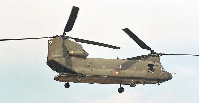
Spanish Army CH-47 Chinook
Tandem
Tandem rotors are two horizontal main rotor assemblies mounted one behind the other with the rear rotor mounted slightly higher than the front rotor. Tandem rotors achieve pitch attitude changes to accelerate and decelerate the helicopter through a process called differential collective pitch. To pitch forward and accelerate, the rear rotor increases collective pitch, raising the tail and the front rotor decreases collective pitch, simultaneously dipping the nose. To pitch upward while decelerating (or moving rearward), the front rotor increases collective pitch to raise the nose and the rear rotor decreases collective pitch to lower the tail. Yaw control is developed through opposing cyclic pitch in each rotor; to pivot right, the front rotor tilts right and the rear rotor tilts left, and to pivot left, the front rotor tilts left and the rear rotor tilts right.
Coaxial
Coaxial rotors are a pair of rotors turning in opposite directions, but mounted on a mast, with the same axis of rotation, one above the other. The advantage of the coaxial rotor is that, in forward flight, the lift provided by the advancing halves of each rotor compensates for the retreating half of the other, eliminating one of the key effects of dissymmetry of lift; retreating blade stall. However, other design considerations plague coaxial rotors. There is an increased mechanical complexity of the rotor system because it requires linkages and swash-plates for two rotor systems. Add that each rotor system needs to be turned in opposite directions means that the mast itself is more complex, and provisions for making pitch changes to the upper rotor system must pass through the lower rotor system.
Intermeshing
Intermeshing rotors on a helicopter are a set of two rotors turning in opposite directions, with each rotor mast mounted on the helicopter with a slight angle to the other so that the blades intermesh without colliding. This configuration is sometimes referred to as a synchropter. Intermeshing rotors have high stability and powerful lifting capability. The arrangement was successfully used in Nazi Germany for a small anti-submarine warfare helicopter, the Flettner Fl 282 Kolibri. During the Cold War, the American company, Kaman Aircraft produced the HH-43 Huskie for the USAF firefighting and rescue missions. The latest Kaman model, the Kaman K-MAX, is a dedicated sky crane design.
Transverse
Transverse rotors are mounted on the end of wings or outriggers, perpendicular to the body of the aircraft. Similar to tandem rotors and intermeshing rotors, the transverse rotor also utilizes differential collective pitch. But like the intermeshing rotors, the transverse rotors use the concept for changes in the roll attitude of the rotorcraft. This configuration is found on two of the first viable helicopters, the Focke-Wulf Fw 61 and the Focke-Achgelis Fa 223, as well as the world's largest helicopter ever built, the Mil Mi-12. It is also the configuration found on tiltrotors, such as Bell's XV-15 and the newer V-22 Osprey.
Tip jets
The most unusual helicopter configuration is the tip jet rotor, where a single main rotor is not driven by the mast, but from nozzles on the tip of the rotor blade; which are either pressurized from a fuselage-mounted gas turbine or have their own pulsejet combustion chambers. Although this method is simple and eliminates torque, the prototypes that have been built lack the fuel efficiency of conventional helicopters along with higher noise levels. Subsequently, none have made it into production.
Helicopter rotor system
The rotor system, or more simply rotor, is the rotating part of a helicopter which generates lift. A rotor system may be mounted horizontally as main rotors are, providing lift vertically, or it may be mounted vertically, such as a tail rotor, to provide lift horizontally as thrust to counteract torque effect. In the case of tiltrotors, the rotor is mounted on a nacelle that rotates at the edge of the wing to transition the rotor from a horizontal mounted position, providing lift horizontally as thrust, to a vertical mounted position providing lift exactly as a helicopter.
The rotor consists of a mast, hub and rotor-blades. The mast is a cylindrical metal shaft which extends upwards from and is driven by the transmission. At the top of the mast is the attachment point for the rotor blades called the hub. The rotor blades are then attached to the hub by a number of different methods. Main rotor systems are classified according to how the main rotor blades are attached and move relative to the main rotor hub. There are three basic classifications: semirigid, rigid, or fully articulated, although some modern rotor systems use an engineered combination of these types. Semirigid
A semirigid rotor system allows for two different movements, flapping and feathering. This system is normally comprised of two blades, which are rigidly attached to the rotor hub. The hub is then attached to the rotor mast by a trunnion bearing or teetering hinge and is free to tilt with respect to the main rotor shaft. This allows the blades to see-saw or flap together. As one blade flaps down, the other flaps up. Feathering is accomplished by the feathering hinge, which changes the pitch angle of the blade. Since there is no vertical drag hinge, lead-lag forces are absorbed through blade bending.
Helicopters with semi-rigid rotors are vulnerable to a condition known as mast bumping which can cause the rotor flap stops to shear the mast. Mast bumping is normally encountered during low-G maneuvers, so it is written into the operator's handbook to avoid any low-G conditions.
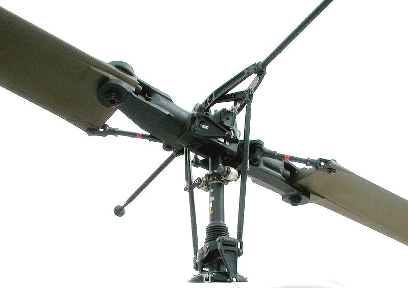
Fully articulated
In a fully articulated rotor system, each rotor blade is attached to the rotor hub through a series of hinges, which allow the blade to move independently of the others. These rotor systems usually have three or more blades. The blades are allowed to flap, feather, and lead or lag independently of each other. The horizontal hinge, called the flapping hinge, allows the blade to move up and down. This movement is called flapping and is designed to compensate for dissymmetry of lift. The flapping hinge may be located at varying distances from the rotor hub, and there may be more than one hinge. The vertical hinge, called the lead-lag or drag hinge, allows the blade to move back and forth. This movement is called lead-lag, dragging, or hunting. Dampers are usually used to prevent excess back and forth movement around the drag hinge. The purpose of the drag hinge and dampers is to compensate for the acceleration and deceleration caused by Coriolis Effect. Each blade can also be feathered, that is, rotated around its spanwise axis. Feathering the blade means changing the pitch angle of the blade. By changing the pitch angle of the blades you can control the thrust and direction of the main rotor disc.
Rigid
In a rigid rotor system, the blades, hub, and mast are rigid with respect to each other. The rigid rotor system is mechanically simpler than the fully articulated rotor system. There are no vertical or horizontal hinges so the blades cannot flap or drag, but they can be feathered. Operating loads from flapping and lead/lag forces must be absorbed by bending rather than through hinges. By flexing, the blades themselves compensate for the forces which previously required rugged hinges. The result is a rotor system that has less lag in the control response, because the rotor has much less oscillation. The rigid rotor system also negates the danger of mast bumping inherent in semi-rigid rotors.
Combination
Modern rotor systems may use the combined principles of the rotor systems mentioned above. Some rotor hubs incorporate a flexible hub, which allows for blade bending (flexing) without the need for bearings or hinges. These systems, called flextures, are usually constructed from composite material. Elastomeric bearings may also be used in place of conventional roller bearings. Elastomeric bearings are bearings constructed from a rubber type material and have limited movement that is perfectly suited for helicopter applications. Flextures and elastomeric bearings require no lubrication and, therefore, require less maintenance. They also absorb vibration, which means less fatigue and longer service life for the helicopter components.
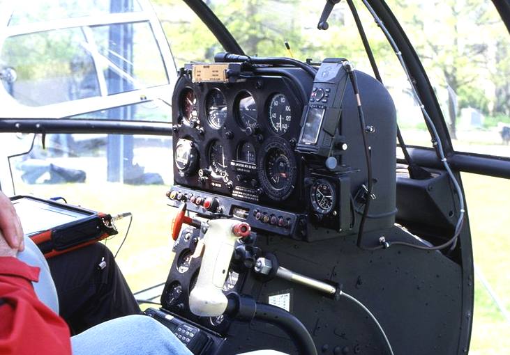
Controlling flight
Useful flight requires that an aircraft be controlled in all three dimensions. In a fixed-wing aircraft this is easy: small movable surfaces are adjusted to change the aircraft's shape so that the air rushing past pushes it in the desired direction. In a helicopter, however, there is often not enough speed for this method to be practical.
For pitch (tilting forward and back) or roll (tilting sideways) the angle of attack of the main rotor blades is altered—cycled—during the rotation creating different amount of lifts at different points in the cycle. This is also how the helicopter is propelled: pitching forward causes forward flight.
For rotation about the vertical axis (yaw) the anti-torque system is used. Varying the pitch of the tail rotor alters the sideways thrust produced. Yaw controls are usually operated with anti-torque pedals corresponding to a fixed-wing aircraft's rudder pedals.
Helicopters maneuver with three flight controls besides the pedals. The collective pitch control lever controls the collective pitch, or angle of attack, of the helicopter blades all together, i.e. equally throughout the 360 degree rotation of the rotor. When the angle of attack is increased, the blade produces more lift. The collective control is usually a lever at the pilot's left side. Simultaneously increasing the collective and adding power with the throttle causes the helicopter to rise.
Dual rotor helicopters follow the same principles, but differ in the following ways:
The throttle controls the power produced by the engine, which is connected to the rotor by a transmission. The throttle control is a motorcycle-style twist grip mounted on the collective control. RPM control is critical to proper operation for several reasons. Helicopter rotors are designed to operate at a specific RPM. However, for each weight and speed there would be an ideal RPM (design-rpm). In practice, a single (higher) RPM is used in order to minimize resonance design requirements and add a safety margin to rotor stall RPM. Usually only in autorotation are different RPMs used to increase rotor efficiency, which can be crucial in the case of an emergency without engine power.
If the RPM becomes too low, the rotor blades stall. This suddenly increases drag and slows the rotor down further. The reduced centrifugal forces are then no longer able to keep the rotor blades straight: excessive coning ("tuliping") develops and a catastrophic accident is certain.
If the RPM is too high, damage to the main rotor hub, power transmission and engine from excessive forces can result. In general, RPM must be maintained within a tight tolerance, usually a few percent, and the RPM indicator dial is marked accordingly. In many piston-powered helicopters, the pilot must manage the engine and rotor RPM. The pilot manipulates the throttle to maintain rotor RPM and therefore regulates the effect of drag on the rotor system. Turbine engined helicopters, and some piston helicopters, use servo-feedback loops in their engine controls to maintain rotor RPM and relieve the pilot of routine responsibility for that task.
The cyclic (pitch control lever) changes the pitch of the blades cyclically, causing the lift to vary across the plane of the rotor disc. This variation in lift causes the rotor disc to tilt and the helicopter to move during hover flight or change attitude in forward flight. The cyclic is similar to a joystick and is usually positioned in front of the pilot. The cyclic controls the angle of the stationary section of the swashplate, which in turn controls the angle of the rotating section of the swashplate. The rotating section rotates with the rotor and is connected to blade pitch horns through pitch links, one link for each blade. When the swashplate is not tilted, the blades are all at the collective angle. When it is tilted, the links give a pitch-up at some azimuthal angle and a pitch-down at the opposite angle, hence creating a sinusoidal variation in blade angle of attack. This causes the helicopter to tilt in the same direction as the cyclic. If the pilot pushes the cyclic forward, then the rotor disc tilts forward, and the rotor produces a thrust in the forward direction.
As a helicopter moves forward, the rotor blades on one side move at rotor tip speed plus the aircraft speed and are referred to as the advancing blades. As the blades swing to the other side of the helicopter, they move at rotor tip speed minus aircraft speed and are referred to as the retreating blades. To compensate for the added lift on the advancing blades and the decreased lift on the retreating blades, the angle of attack of the blades is regulated as they spin round. The angle of attack is increased on the retreating blade to produce more lift, compensating for the slower airspeed over the blade; the angle of attack is decreased on the advancing blade to produce less lift, compensating for the faster airspeed over the blade.
If the angle of attack of any wing, or rotor blade, is too high, the airflow above it separates and this causes an instant loss of lift and increase in drag. This condition is called aerodynamic stall. On a helicopter, this can happen in any of four ways.
Helicopters are powered aircraft, but to a limited extent they can glide without power by using the momentum in the rotors, while using downward motion to force air through them. The main rotor acts like a windmill and turns. This technique is known as autorotation. A transmission connects the main rotor to the tail rotor so that all flight controls are available after engine failure. Autorotation can allow a pilot to make an emergency landing if the engine failure occurs while the helicopter is traveling high enough or fast enough.
Stability
Fixed wing aircraft are usually inherently stable. If a gust of wind or a nudge to one of the controls causes a fixed wing aircraft to pitch, roll, or yaw, the aerodynamic design of the aircraft will tend to correct the motion, and the aircraft will return to its original attitude. Many small, fixed wing aircraft are stable enough that a pilot can let go of the controls while looking at a map or dealing with a radio, and the plane will generally stay on course.
In contrast, helicopters are very unstable. Simply hovering requires continuous, active corrections from the pilot. When a hovering helicopter is nudged in one direction by a gust of wind, it will tend to continue in that direction, and the pilot must adjust the cyclic to correct the motion. Hovering a helicopter has been compared to balancing yourself while standing on a large beach ball.
Adjusting one flight control on a helicopter almost always has an effect that requires an adjustment of the other controls. Moving the cyclic forward causes the helicopter to move forward, but will also cause a reduction in lift, which will require extra collective for more lift. Increasing collective will reduce rotor RPM, requiring an increase in throttle to maintain constant rotor RPM. Changing collective will also cause a change in torque, which will require the pilot to adjust the foot pedals.
Small helicopters can be so unstable that it may be impossible for the pilot to ever let go of the cyclic while in flight. While fixed-wing aircraft are generally designed so pilots sit on the left side of the aircraft, freeing up their right hand for dealing with radios, engine controls, and the like, helicopters are generally designed so pilots sit on the right side of the aircraft so they can keep their right hand (usually the strong hand) on the cyclic at all times, leaving the radios and engine controls for their left hand (usually the weaker hand).
Limitations
The single most obvious limitation of the helicopter is its slow speed. There are several reasons why a helicopter cannot fly as fast as a fixed wing aircraft.
During the closing years of the 20th century designers began working on helicopter noise reduction. Urban communities have often expressed great dislike of noisy aircraft, and police and passenger helicopters can be unpopular. The redesigns followed the closure of some city heliports and government action to constrain flight paths in national parks and other places of natural beauty.
Helicopters vibrate. An unadjusted helicopter can easily vibrate so much that it will shake itself apart. To reduce vibration, all helicopters have rotor adjustments for height and pitch. Most also have vibration dampers for height and pitch. Some also use mechanical feedback systems to sense and counter vibration. Usually the feedback system uses a mass as a "stable reference" and a linkage from the mass operates a flap to adjust the rotor's angle of attack to counter the vibration. Adjustment is difficult in part because measurement of the vibration is hard. The most common adjustment measurement system is to use a stroboscopic flash lamp, and observe painted markings or coloured reflectors on the underside of the rotor blades. The traditional low-tech system is to mount coloured chalk on the rotor tips, and see how they mark a linen sheet.
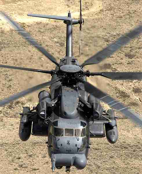
Sikorsky MH-53
Hazards of helicopter flight
As with any moving vehicle, operation outside of safe regimes could result in loss of control, structural damage, or fatality. For helicopters the hazards are particularly acute since they are often flying at relatively low altitude, with little time to react to a sudden event. The following is a list of some of the potential hazards for helicopters:
References
AVIATION A - Z
Solarnavigator is designed to carry the Scorpion anti pirate weapon. A fleet of such autonomous vessels could be the basis of an international peacekeeping, and/or emergency rescue force. The navigation system that is being developed for SolarNavigator could have prevented the sinking of the Costa Concordia and Baltic Ace. This might be of interest to fleet operators.
|
||
|
This website is Copyright © 1999 & 2013 Max Energy Limited an educational charity working hard for world peace. The bird logos and names Solar Navigator, Blueplanet Ecostar and Utopia Tristar are trademarks. All rights reserved. All other trademarks are hereby acknowledged. |
||
|
AUTOMOTIVE | BLUEPLANET BE3 | ELECTRIC CARS | ELECTRIC CYCLES | SOLAR CARS | SOLARNAVIGATOR | UTOPIA |