|
WIND TUNNELS
|
|
HOME | BIOLOGY | BOOKS | FILMS | GEOGRAPHY | HISTORY | INDEX | INVESTORS | MUSIC | NEWS | SOLAR BOATS | SPORT |
|
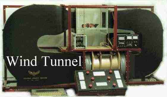
The designer of BE1, 2 & 3, built a series of small wind tunnels to refine the aerodynamics of his vehicles. The tunnel shown below was the last. It could accommodate 1/25th scale models. If you look closely a model of the BE1 is seen in the transparent observation module.
Nelson says - "build your own instruments"
Nelson says: "A basic understanding of fluid dynamics is essential for every vehicle designer. Whether you are building a land speed record car, or a hyper efficient town buggy, you must have an idea of the forces acting upon the vehicle to achieve best results. Unfortunately, this is a highly specialised engineering field and somewhat of a black art."
"I decided to build my first wind tunnel just to get the feel for it. I'm glad I did. The first plywood tunnel I built was an open ended affair and took only a few days at a cost of £50." (Note 1980s prices)
"The closed circuit model shown on this page had a tubular steel support frame and welded aluminum tunnel walls. It took around three months to build, with a lot of delving into electronics, thereafter, at a total cost of £6,000." (Note: 1990s prices)
Nelson's Mk2 wind tunnel - electronic measurement, a development tool: BE1 in the measuring chamber.
Strain gauges provided measurement of drag, lift and down-force. A rotating table was incorporated so vehicle models could be tested in side wind conditions. Air temperature and wind speed were also monitored and smoke could be trailed over models to visualize airflow, to highlight problem areas. This tunnel could fit comfortably on an office desk. It measured just 60" x 40" x 15". Being a closed circuit design it was not unbearably noisy in operation.
A wind tunnel is a complex piece of engineering. The Wright Brothers were the first inventors to use such a tool to compile lift and drag tables for various wing shapes. It is much more difficult to design a balance to measure lift and down-force on each wheel of a vehicle. When working at such a small scale, accuracy of measurement is essential. Fortunately, electronics come to the rescue, with compensated amplifiers providing multiplication of movement up to a thousand.
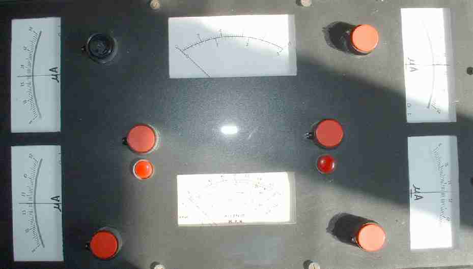
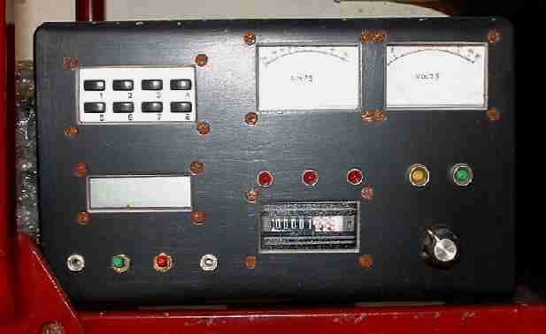
Wind tunnel instrument display - Lift/down force, drag and wind speed
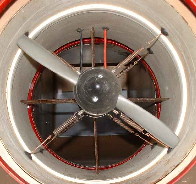
The key component of any wind tunnel is the fan assembly. Take a look at the propeller and motor above. In is mounted on eight springs to reduce vibration. The whole fan module is then positioned on rubber mounts, which in turn channel vibration through a plywood frame. The net effect is to pass the vibration through materials with different natural frequencies, so acting as a vibration filter, much like coils and capacitors are used to filter out unwanted frequencies in Hi Fi speaker systems. Lead weights are also employed to give mass to the base frame unit.
In fluid dynamics, a streamline is a line which is everywhere tangent to the velocity of the flow. This can be contrasted with a pathline, which is the trajectory that an imaginary infinitesimally small point would make if it followed the flow of the fluid in which it was embedded, and a streakline, which is the current location of all fluid particles that have passed through a particular spatial point in the past. In steady (time-independent) flow, the streamlines, pathlines, and streaklines coincide. A scalar function whose contours define the streamlines is known as the streamfunction.
Streamlines are frame-dependent. That is, the streamlines observed in one inertial reference frame are different from those observed in another inertial reference frame. For instance, the streamlines in the air around a aircraft wing are defined differently for the passengers in the aircraft than for an observer on the ground. When possible, fluid dynamicists try to find a reference frame in which the flow is steady, so that they can use experimental methods of creating streaklines to identify the streamlines. In the aircraft example, the observer on the ground will observe unsteady flow, and the observers in the aircraft will observe steady flow, with constant streamlines.
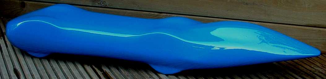
Nelson's Blueplanet Ecostar Electric BE3 - wind tunnel model
By definition, streamlines defined at a single instant in a flow do not intersect. They cannot begin or end inside the fluid. A region bounded by streamlines is called a stream tube. Because the streamlines are tangent to the flow velocity, fluid that is inside a stream tube must remain forever within that same stream tube.
Knowledge of the streamlines can be useful in fluid dynamics. For example, Bernoulli's principle, which expresses conservation of mechanical energy, is only valid along a streamline. Also, the curvature of a streamline is an indication of the pressure change perpendicular to the streamline. The instantaneous center of curvature of a streamline is in the direction of increasing pressure, and the magnitude of the pressure gradient can be calculated from the curvature of the streamline.
Engineers often use dyes in water or smoke in air in order to see streaklines, and then use the patterns to guide their design modifications, aiming to reduce the drag. This task is known as streamlining, and the resulting design is referred to as being streamlined. Streamlined designs, like steam locomotives, streamliners and human bodies are often esthetically pleasing to the eye.
The Streamline Moderne style, an 1930s and 1940s offshoot of Art Deco, brought flowing lines to architecture and design of the era. The canonical example of a streamlined shape is a chicken egg with the blunt end facing forwards. This shows clearly that the curvature of the front surface can be much steeper than the back of the object. Most drag is caused by eddies in the fluid behind the moving object, and the objective should be to allow the fluid to slow down after passing around the object, and regain pressure, without forming eddies.
The same terms have since become common vernacular to describe any process that smooths an operation. For instance, it is common to hear references to streamlining a business practice, or operation.
Spring mounted 1hp fan motor
WIND TUNNEL TECHNICAL
A wind tunnel is a research tool developed to assist with studying the effects of air moving over or around solid objects.
Air is blown or sucked through a duct equipped with a viewing port and instrumentation where models or geometrical shapes are mounted for study. Various techniques are then used to study the actual airflow around the geometry and compare it with theoretical results, which must also take into account the Reynolds number and Mach number for the regime of operation.
For example:
A vertical wind tunnel is a recreational facility for indoor skydiving.
Nelson's wind tunnel control panel: temperature, hours run amps and volts (=watts), and variable speed control.
The key component of any wind tunnel is the fan assembly. Take a look at the propeller and motor above. In is mounted on eight springs to reduce vibration. The whole fan module is then positioned on rubber mounts, which in turn channel vibration through a plywood frame. The net effect is to pass the vibration through materials with different natural frequencies, so acting as a vibration filter, much like coils and capacitors are used to filter out unwanted frequencies in Hi Fi speaker systems. Lead weights are also employed to give mass to the base frame unit.
It is necessary to have variable speed control of the main fan unit. The control panel above shows temperature gauge, amp and volt meters for the main motor and hours run meter. There are other switches for smoke trails, etc.
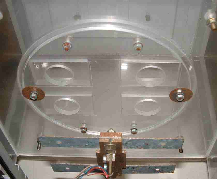
Plexiglas test chamber viewed from underneath, minus pushrods to the 5 element strain gauge balance.
Strain gauges provided measurement of drag, lift and down-force. A rotating table was incorporated so vehicle models could be tested in side wind conditions. Air temperature and wind speed were also monitored and smoke could be trailed over models to visualize airflow, to highlight problem areas. This tunnel could fit comfortably on an office desk. It measured just 60" x 40" x 15". Being a closed circuit design it was not unbearably noisy in operation.
A wind tunnel is a complex piece of engineering. The Wright Brothers were the first inventors to use such a tool to compile lift and drag tables for various wing shapes. It is much more difficult to design a balance to measure lift and down-force on each wheel of a vehicle. When working at such a small scale, accuracy of measurement is essential. Fortunately, electronics come to the rescue, with compensated amplifiers providing multiplication of movement up to ten thousand.
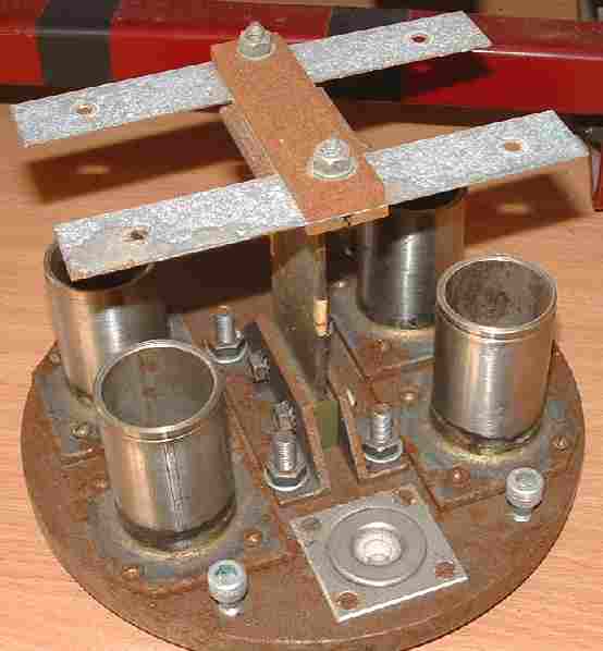
Five element balance with oil large damping units (slightly the worse for wear)
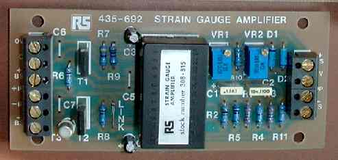
Five of the above RS strain gauge amplifiers gave separate channels of information to provide a range of measurements to include drag, lift and down-force for each wheel.
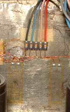
Each amplifier is fed information from a bridge of four foil resistors bonded to each element of the balance, two on each side. There are five elements to the balance, consequently, you will need quite a few (20) strain gauges and some patience during the epoxy bonding and positioning. The marking out must be exceptionally accurate.
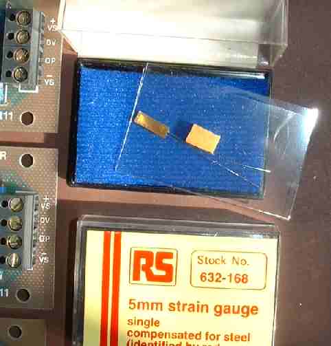
Single laser cut 5mm strain gauge - foil resistor
The components used in the above tunnel, were not exactly cheap if you are on a small budget, but more importantly, with suppliers such a Radio Spares (RS) they at least are widely available to amateur scientists and enthusiasts.
Strain gauges (laser cut resistor grids) bonded to steel element - 2 on each side wired as a wheatstone bridge.
LINKS:
RS strain gauge amplifier. The balance uses 5 of these.
WINDMILL LINKS | WIND TURBINES | SUSSEX WINDMILL RESTORATION
New energy drinks for performers .. Thirst for Life
330ml Earth can - the World in Your Hands
|
|
This
website
is Copyright © 1999 & 2013 Electrick Publications.
The blue bird The name '1824' is a trade mark of Solar Cola Ltd. All rights reserved. Max Energy Limited is an educational charity. |
|
AUTOMOTIVE | BLUEPLANET | ELECTRIC CARS | ELECTRIC CYCLES | SOLAR CARS | SOLARNAVIGATOR | UTOPIA |