|
|
|||||||||
|
1/10th scale SWATH (Cat twin hull) MODEL DEVELOPMENT
In 1993 the designer of the boats shown here used a large map of the world and a series of insolation graphs provided by BP, with which he calculated that a solar powered boat would be able to circumnavigate the globe using only energy from nature. It was a bit of reverse engineering. He knew what energy could be collected at certain waypoints around the planet, from where he designed a vessel that could capture enough energy to overcome hull resistance for sea states that were bound to be encountered - even tropical revolving storms. This is the key formula. You need a hull design with a good power to weight ratio that is capable of standing up to the oceans of the world.
He displayed the first of his development models at the Earls Court boat show in London in 1994/5.
BOAT BUILDING
If you are going to build custom designs like these boats, you will need a good range of boat-building skills to include sheet metal cutting and forming (bending), welding, pop-riveting, woodwork/joinery and composite handling.
You also need a keen eye and drawing skills to loft the scale paper drawings onto sheet materials such a plywood, chipboard and aluminium. Then workshop theory and practice takes over. So, you'll need a reasonably well equipped work place and plenty of room away from distractions. Many people overlook basic equipment such as cutting tables, benches and vices. Without them, you will struggle - perhaps on the kitchen or snooker table.
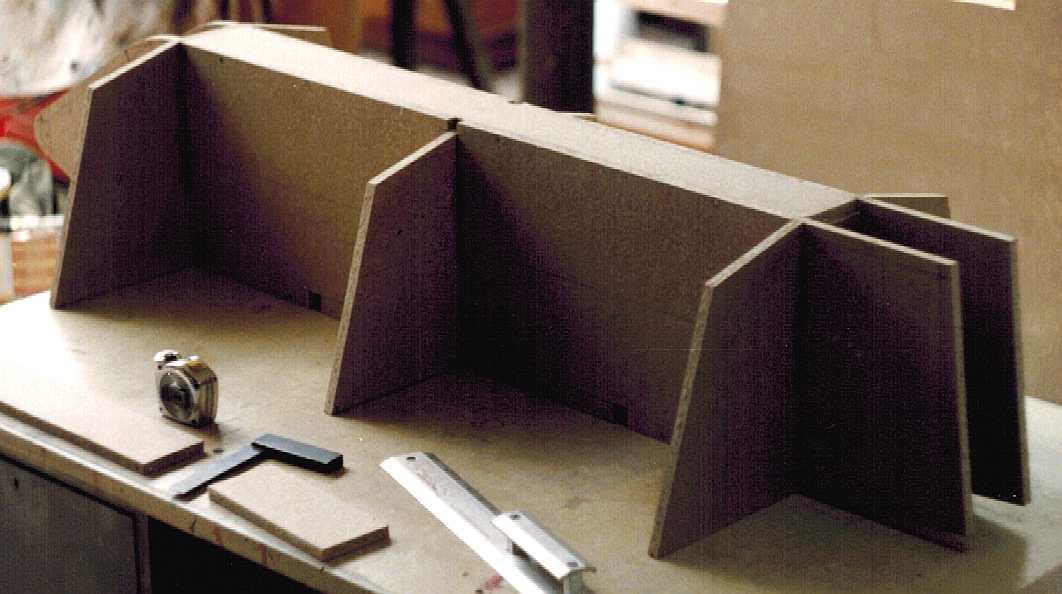
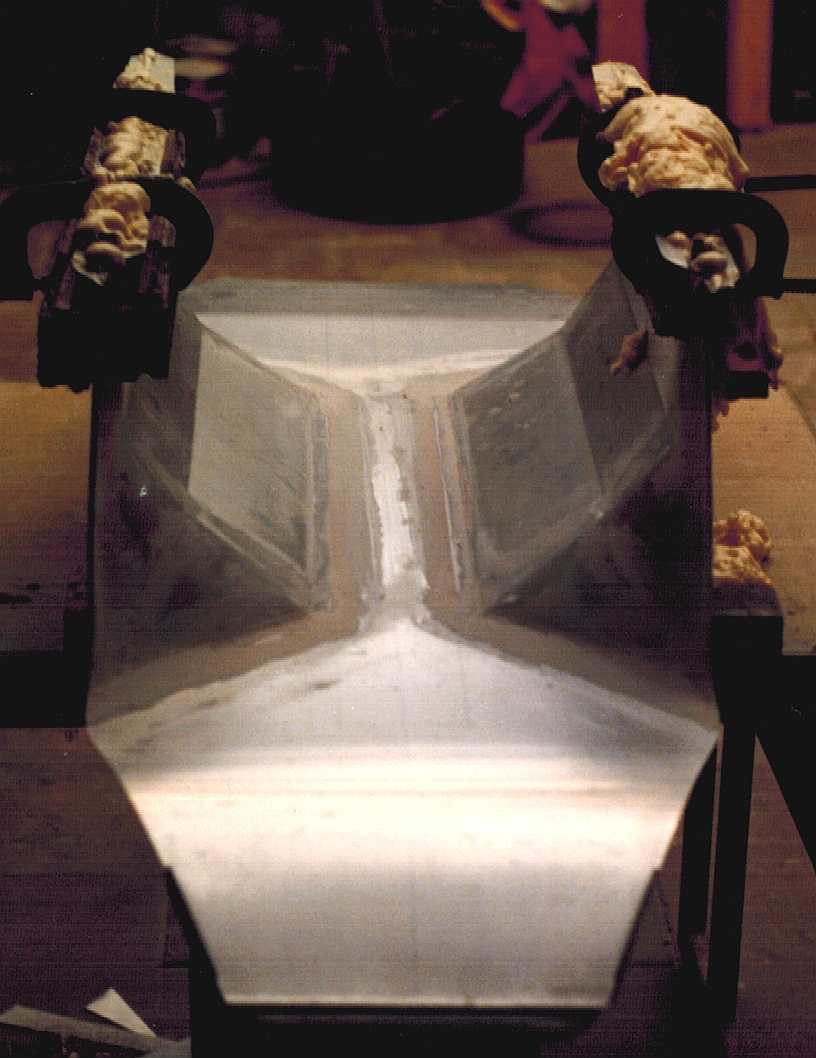
THE SUPERSTRUCTURE
This is not the actual superstructure, it would be far too heavy made of chipboard. This is the pattern from which a mould will be made. Chipboard is cheap and robust enough for patterns. These days MDF is preferred, but this was early 1994. Two identical full length patterns form the basic box into which transverse bulkheads are slotted.
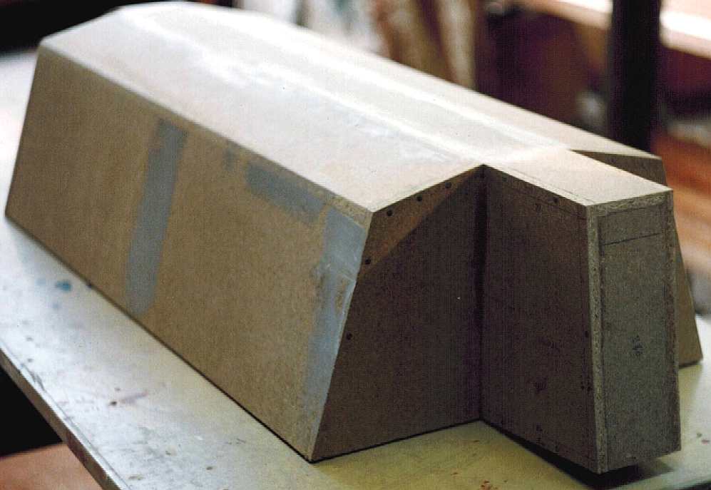
Here we have the top and sides in filled. Where there are chips or other defects in the chipboard, polyester body filler is used as a leveler.
The tricky aft section are added. These need three more sections a side to complete the rear of the mould. The whole superstructure will then receive several resin gel coats, then sanded to level perfection. Once the master (buck) is completed, it will be waxed several times to ensure release, from the grp that will be applied with reinforcing ribs to prevent distortion.
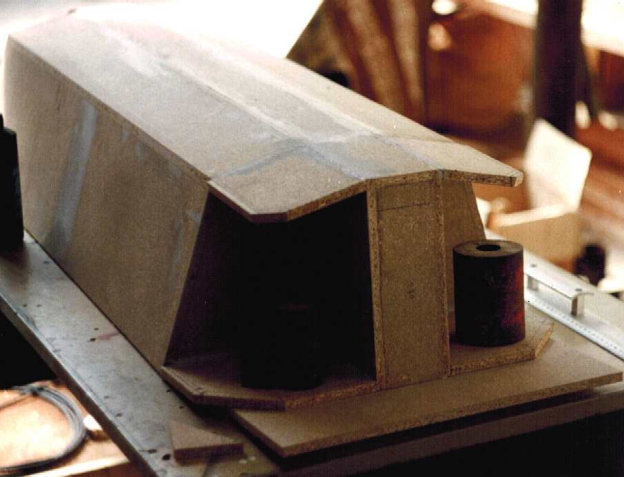
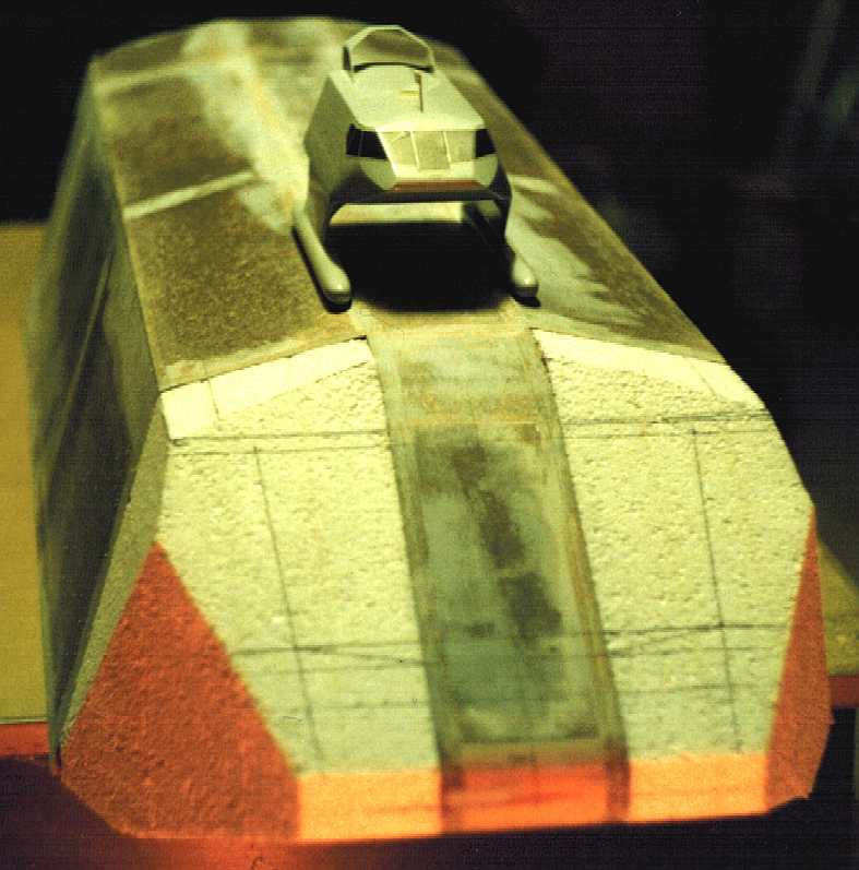
For the helm, a different method is used, because there were a couple of angles that would be difficult to get just right with chipboard sections. Polystyrene blocks are bonded to the chipboard and the windscreens carefully marked. You can see from the smaller model perched on the deck of the buck, that the next angled cuts on the left and right will be easier with a wood saw and shaving block, than trying to work out the radii for wooden panels. Once carved polystyrene needs to be sealed to prevent the solvents from the polyester resin from melting the substrate. The superstructure is common to MKI and MKII hulls.
THE HULL NOSE CONES
Both the superstructure and hull nose/tail cones are common to the MKI and MKII Solar Navigator SWATH test models. Just as much work goes into producing a small item like this, as goes into producing a typical boat hull, and that is why submarines are more expensive; they are simply more complicated.
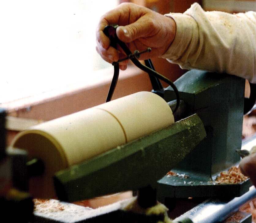
A softwood blank is prepared from a 4" x 4" section, then turned by a local craftsman, until the profile matched that he was asked to produce. Thanks Bill.
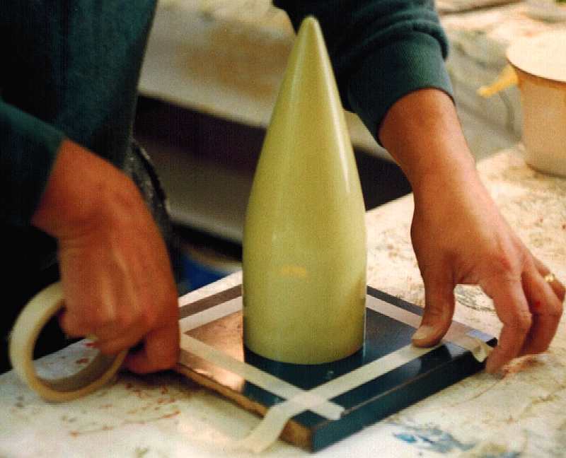
The turned wood is coated with several layers of gel-coat and hand finished until it is perfectly smooth. Several coats of release wax are applied and polished to ensure that the fiberglass will come away from the plug. The plug is then attached to a formica surfaced board and masking tape applied to define an area. A cone like this can cause release problems, especially where it is so deep.
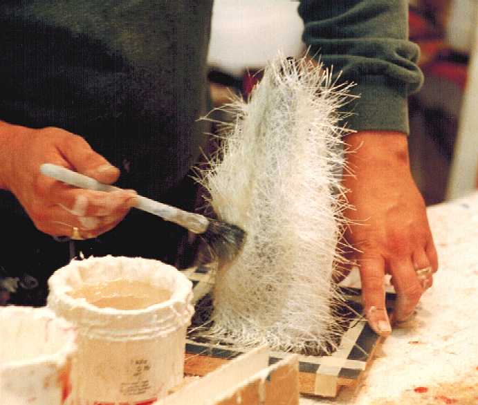
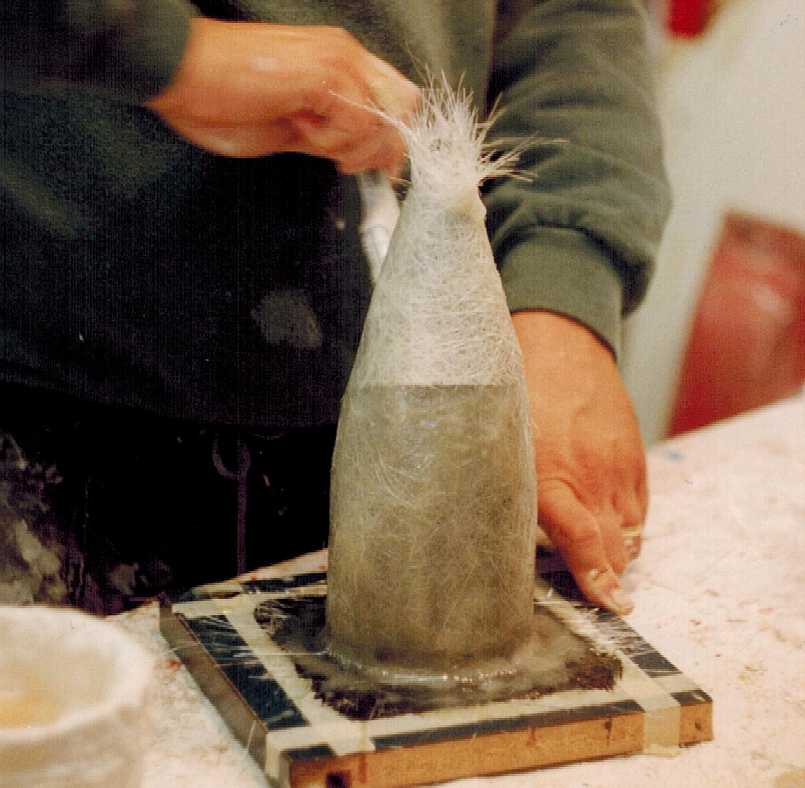
Polyester resin is applied with layers of 600gsm chopped strand glass matting. A brush is used to wet the matting thoroughly and then a roller is used to remove any trapped air bubbles. Once this has cured, the inside of the mold created is polished with release wax and lay-up is then the reverse procedure, with resin and matting applied inside the mold. In fact we had to repeat this procedure again, introducing a lip on the second mould produced, which was this time a split (two-piece) mold - held together with four quick-release wing nuts - ideal for a production run.
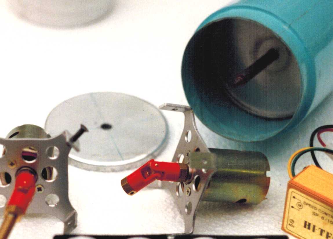
A nose cone taken from the molds produced above is seen in blue. Inside is fitted a circular aluminium bulkhead through which a brass propeller tube passes, so that alignment for the universal joints is within acceptable limits. The nose and tail hull cones are common to MKI and MKII hulls.
SWATH MKI FOILS
The MKI SWATH vessel was not as successful as he'd hoped. Sure, it worked, but it was relatively unstable and redistributing weight about the hull, combined with trimming could not cure a basic flaw in design. The calculations were too fine for his liking, the centre of flotation too high. That mistake was a valuable lesson learned the hard way - by doing. He took what he'd learned and applied that knowledge to his MKII. And that is a quality that you will need to nurture as a boat builder/designer: temperance.
There is a big difference in construction techniques between MKI and MKII SWATH hulls. The MKI is built of aluminium, and mostly pop riveted as you can see from the photo sequence below.
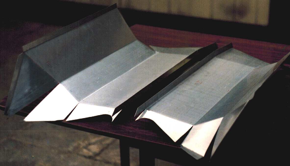
Using 1.0mm ally sheet, mirror image developments of the leg foils are cut and folded.
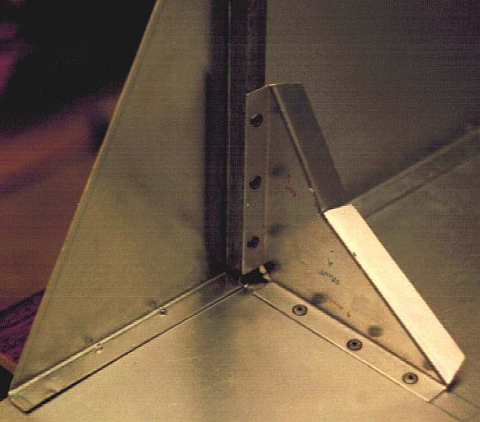
Aluminium is a joy to work with, though it marks easily when cutting with a jig-saw, it folds beautifully. Fine felt tip pens are used to mark out the sheet metal before cutting. Four of these reinforcing angle brackets were used to give form to the sea foils.
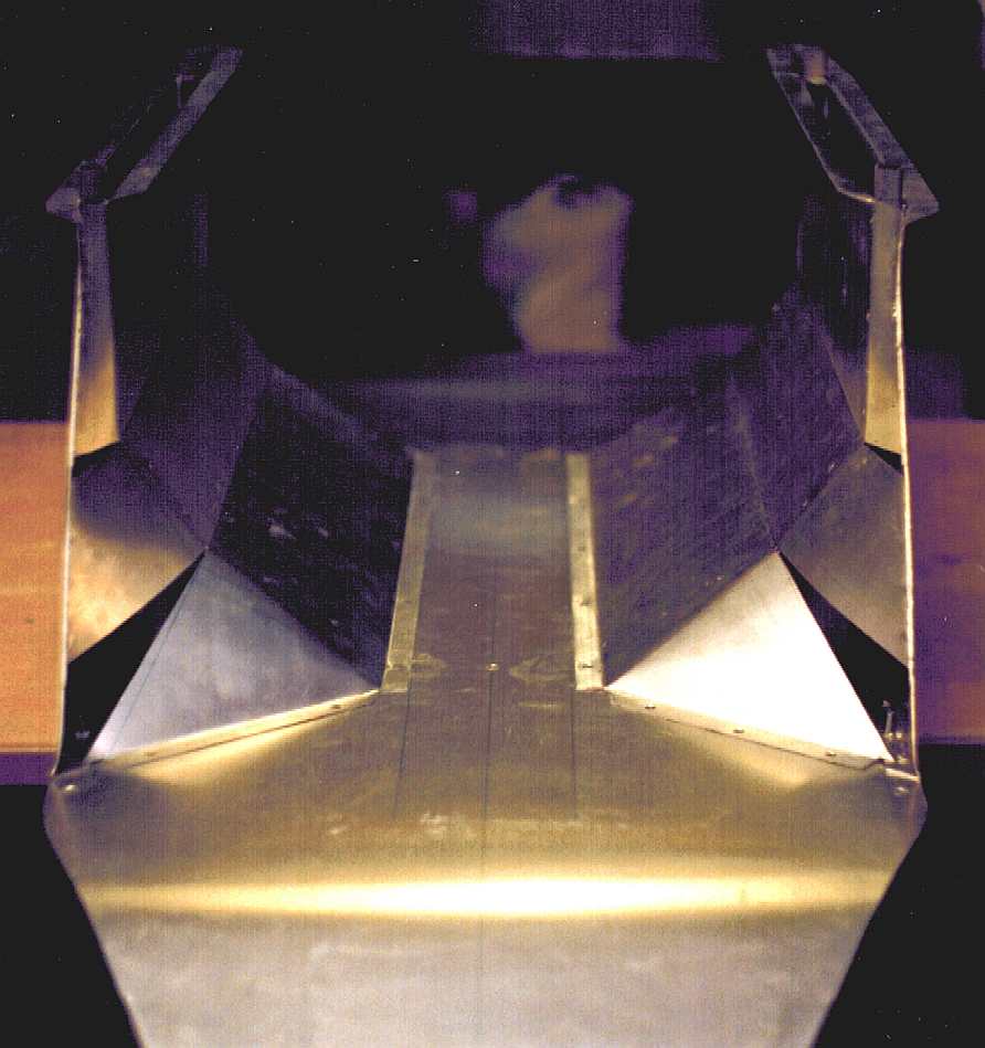
One large aluminium sheet section is used for the underside of the hull (shown here upside down on a workbench). You can see the guide markings in different color felt pens. Always mark everything, with centre guidelines, even if you don't need them. They may help you later on. Offer up the parts to be sure they fit perfectly before getting out the rivet gun. If you do something on one side, be sure to do it on the other, even if you learned a better way from the first. The wing developments are riveted in place.
The aluminium legs are filled with expanding polyurethane foam. You can't be too careful at sea. Even a model should be made as sink-proof as possible. Once this stage was reached the hull tubes were also pop-riveted in place: aluminium to plastic, with a mastic join as a fail-safe water seal. You'd be surprised how string adhesives like "no-nails" bond. On another model it proved impossible to part an alloy bracket from a composite hull. Begging the question; why use pop rivets at all?
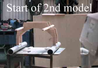
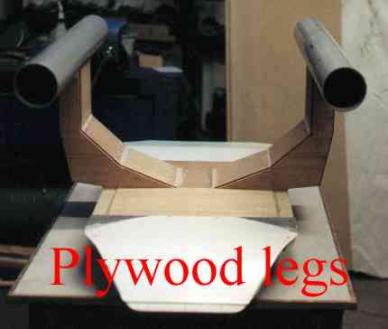
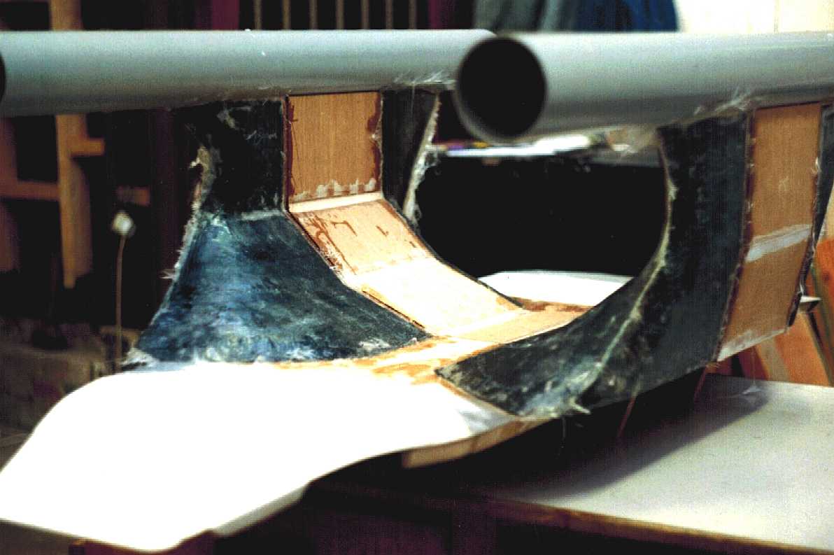
SWATH MKII FOILS
The MKII is mostly wood and composites, except for the submerged hull tubes, which are a heavy duty plastic used in laying underground electrical cables, and are common to both developments.
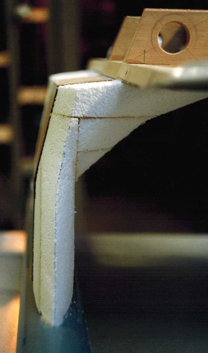
It is completely different working with composites. Unlike the superstructure and hull cones, we did not want to make moulds for the legs, using instead a prototyping method, where the item is first carved in foam, just slightly smaller than the finished piece, so that when the matting and resin is applied, it will give the exact outside dimensions as per the design drawings.
This is what it looks like when the foam core is layered on top with woven roving and in this case epoxy resin, for a bit more strength than polyester resin, where the lamination is very thin to save weight. Using this method a surface layer of polyester filler is applied, shaped and sanded to give a nice finish. The whole hull is then primed and painted. In this case in 2-pack paint, which is far more durable than synthetic or cellulose based paints. It is a good idea to coat the plywood in resin at the same time.
DESIGN CONSIDERATIONS
With a boat the most important component on the agenda is the hull. Solar powered boats provide marine architects with new challenges. There are as yet no conventions. Nobody knows what will work best, because so little has been put to the test. We can attest to that because we've tried 5 hull designs to date, improving on each one. Two SWATH designs (one above), two catamarans and a trimaran. The 6th design is not strictly speaking a trimaran, it does though have three hulls; so we're billing it as a trimaran. A hull design like this has not been built to date, to overcome the ever present drag and wave drag dilemma.
The other major challenge is panel design. How do you increase panel area and get as much of it facing the sun when the sun moves relative to the route, and of course keep the boat stable in all seas. We wanted at least 2 kilowatts per ton of vessel mass and can comfortably achieve that. Not to detract from the incredible achievements of the PlanetSolar team, but the SolarNavigator project aims to improve on the record 0f 585 days set in May 2012 with our brand new design. Our advantage is that we have more than twice the power to weight ratio of the current record holder with a lower drag hull. This needs to be verified before we can go to the construction stage.
This project represents a unique opportunity for any global company with eco friendly ambitions. If this is of interest to you please let Blueplanet Productions know using the contact details below. See the breathtaking video of PlanetSolar below to get a handle on the sort of publicity that Solarnavigator can generate.
Planet Solar docking in Hong Kong
On the 4th of May 2012 the theory was proven to be correct by Raphael Domjan and his superb boat the Turanor Planetsolar, thanks to generous sponsorship by Candido Swiss watches and Immosolar, leaders in the field of solar energy management.
Now the benchmark has been set, it will undoubtedly inspire others. As with so many things once a pioneer has shown the way, inevitably, the record stands like mountain to be scaled.
FOR DETAILS OF THE LATEST MODEL BUILD FOLLOW THE BLUEFISH LINK AT THE FOOT OF THIS PAGE
The latest autonomous vessel is a battery electric trimaran in SWASH format with an extremely efficient active hull that runs on solar and wind power. The model shown here is just 150mm long and made of paper and cardboard. It does though float and at the correct level of submersion - hence, for a pew pence the concept was proven in principle. The radio controlled and robotic test models are approximately 3000mm long and made from aluminium and carbon fibre.
Email: bluefish@bluebird-electric.net or phone UK:
+ 44 1323 831727 (no messages on this service) +44 7842 607865
Solar House, BN27 1RF, United Kingdom
|
|||||||||
|
This website is copyright © 1991- 2014 Electrick Publications. All rights reserved. The bird logo and names Solar Navigator and Blueplanet Ecostar are trademarks ™. The Blueplanet vehicle configuration is registered ®. All other trademarks hereby acknowledged and please note that this project should not be confused with the Australian: 'World Solar Challenge'™which is a superb road vehicle endurance race from Darwin to Adelaide. Max Energy Limited is an educational charity.
|
|||||||||