|
WRIGHT BROTHERS WIND TUNNEL
|
|||
|
The wind tunnel had been invented in England in 1871by Francis Wenham and John Browning, who used it to study both wing camber and aspect ratio. Over the next three decades, several other experimenters used it for aeronautical research, mostly in Europe. The 1901 Wright wind tunnel was the second or the third in America.
It's telling that the Wright brothers built their wind tunnel and balances and began collecting data before they had a clear understanding of aerodynamic forces or the measurements they wanted to make. Prior to the January 1902, the terms that Wilbur uses to describe aeronautical forces aren't clearly defined in his mind, and he makes conflicting statements. In all fairness to Wilbur, this is not just a measure of his initial confusion but also the confusion that existed in the field at the time. The components of lift and drag were hotly debated, terms had various meanings depending on how they were used and who was using them. But it's also a good example of how the Wright brothers best worked through a problem. They were "hands on" investigators. To figure out what they were going to measure, they started making measurements.
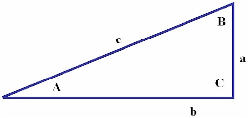
If you are unfamiliar with trigonometry, here's a quick primer. "Trig" depends on ratios called sines, cosines, and tangents - one side of a right angle triangle divided by another. For a triangle with sides a, b, and c and angles A, B, and C as shown, the ratios are as follows:-
Right angle triangle
These ratios are different for each angle but remain constant with size -as long as the angles between the sides remain the same, the ratios are unchanged same no matter what the size of the triangle. Consequently, if you know the magnitude of just one side and one angle (other than the right angle), you can calculate the other two sides by looking up the sine, cosine, and tangent ratios of the known angle and multiplying the appropriate ratio times the known side.
"Normal" was used in the Wright's day much the same way we use "perpendicular" today. The normal force was lift perpendicular to the wing chord. True lift was parallel to the force of gravity and perpendicular to the horizon. Because the wing usually flew at an angle of incidence (our modern angle of attack) that was not parallel to the horizon, the normal force was often at an angle to true lift and the force of gravity. When added up, the forces on the wing resolved themselves into the resultant pressure. Many aeronautical investigators considered that this pressure must correspond with true lift, but Wilbur thought it must be angled slightly forward of lift to compensate for head resistance -- what we now call parasitic drag. The tangential was calculated from the angle between the resultant pressure and the normal force by multiplying the tangent times the normal force: When the angle of incidence was positive (the normal was behind the resultant pressure), the tangential was considered to retard the forward motion of the aircraft and it was added to the drift (drag) to arrive at total resistance. When the angle of incidence was negative (the normal was ahead of of the resultant pressure), the tangential was part of the force that propelled the aircraft and it was subtracted from the drift. Thinking this through, Wilbur added another wrinkle. On any given wing shape, lift did not begin when the chord was parallel to the wind -- it began when the wing was positioned at a slightly negative angle of incidence (attack). This was the zero of lift. Wilbur suggested that the true normal be calculated from the zero of lift rather than the chord. He also suggested that the true tangential should be calculated from the angle between the resultant pressure and the true normal. But after he had finally gotten his mind around all these confusing concepts, Wilbur seemed to see them for what they were -- overthinking the problem. Much of his brilliance was his ability to simplify. Wilbur declared lift and drag to be the keys to aeronautical design and went with his convictions. History has shown that it was a good call -- modern aeronautics has nothing like the tangential.
In the Wilbur and Orville's time, aeronautical investigators studied two distinct types of flight -- soaring flight and dynamic flight (what we now refer to as gliding flight and powered flight). Scientists considered both types to be similar, but the forces in play and the mathematics used to analyze them were somewhat different. Wilbur and Orville were squarely in the soaring camp in 1901. In fact, there is no real evidence to suggest that they planned to attempt dynamic flight at this time, although Wilbur sometimes discussed its theory with Chanute. But they never performed a single experiment that had a direct application to dynamic flight until late October 1902. Their 1901 wind tunnel tests, the forces they measured, and the tables they compiled were all designed to solve problems in soaring flight. One example of this is the importance they placed in the lift/drag ratio. This number was central to the performance of a glider -- the higher the ratio (more lift, less drag), the better the gliding angle irregardless of the weight of the glider and its pilot. The Wrights were perhaps the first to understand this.
Initially, the brothers cut the plate into five fingers. But when they mounted the fingers on the balance, they found one of the fingers near the frame was affected by eddies in the wind coming off the frame. They removed this finger, cut it in two and soldered the parts to two of the remaining fingers. This accounts for the seemingly random length of the fingers. In their final tests, the Wrights used some air foils with 8 square inches of surface area -- a third more than the drag fingers. To compensate, they added another third of the sine of to find the coefficient of lift:
Each balance had two pointers, but just one was used to indicate the angle on the scale. The second pointer balanced the force of the wind hitting the first pointer and kept it from affecting the measurement.
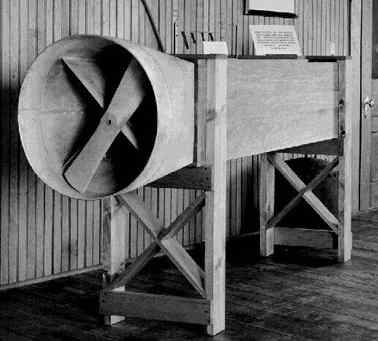
Wright Brothers' - Wind Tunnel propeller
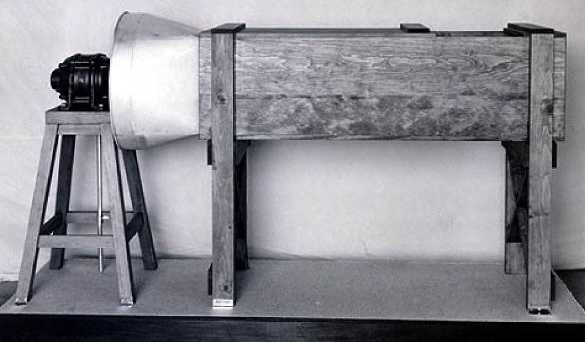
Wilbur's original estimate of the wind speed in the tunnel was 40 feet per second, or about 27 miles per hour. Later, his estimate was revised downward to 25 miles per hour. This velocity would have been very difficult to achieve given the equipment the Wrights were using. When we reproduced the wind tunnel and duplicated the experiments, we used a four-bladed balanced fan running within 10 percent of its maximum safe speed. This produced airflow in the tunnel of 20.3 miles per hour. The Wrights were using a homemade fan with just two blades. It was not dynamically balanced and could not have run for long periods of time at speeds in excess of ours without flying apart. Even if it held together, the vibration at high speeds would have interfered with the experiments. While he was engaged in the wind tunnel tests, Wilbur commented to Octave Chanute that the Richards anemometer they had used at Kitty Hawk (and probably used for the wind tunnel tests) recorded high. Taking all this into account, it's likely that the wind blowing through the Wright's tunnel was less that 20 mph.
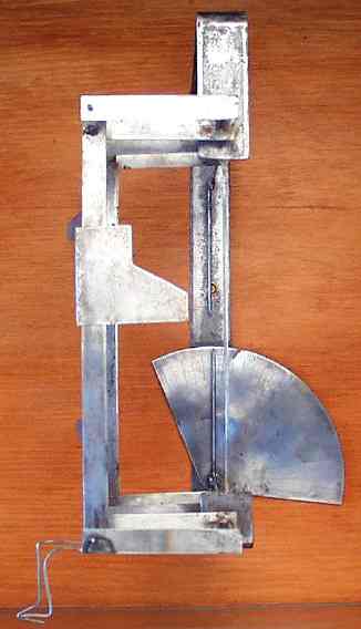
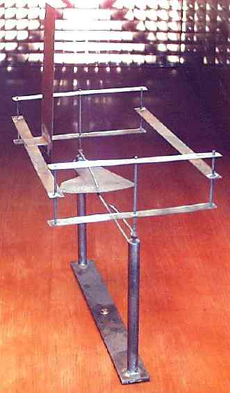
The Wrights called this their "tangential measuring machine." Because they rotated the entire balance, including the scale, the pointer indicated an angle that expressed the ratio of lift to drift minus the angle of incidence (attack). This was essentially the angle used to calculate Lilienthal's tangential force. To get the ratio of true lift to true drift, they had to add the angle of incidence to the angle indicated on the pointer. They sometimes called this the gliding angle, not to be confused with the modern definition of the term, which describes the angle at which a glider descends through the relative wind.
There is no written record that the Wright brothers actually made these calculations to establish the value of the coefficient of pressure. Wilbur had already written Chanute that he suspected the answer was .0033; this was the number that best explained the lift and drag he and Orville had measured when flying their 1901 glider at Kitty Hawk. But with the wind tunnel experiments, the Wright brothers had developed into world-class scientists. It's inconceivable that they wouldn't have taken this final step to confirm their hunch.
The reasoned approach the Wright Brothers took to solving the problem of flight and the diligence with which they pursued their goal is not generally appreciated. The science of aerodynamics, the physics as described by mathematical equations, had been codified centuries earlier by men such as Newton, Bernoulli, Euler, Navier, and Stokes; men who's names are attached to some of the fundamental equations of fluid dynamics. However, not until the Wright Brothers had anyone successfully conquered the engineering - turning the science into an airplane of practical use. Beginning in 1899, Wilbur and Orville executed a research and development program that resulted in not just the 1903 Flyer, but in the first truly practical heavier-than-air flying machine in 1905.
The Wrights gained a thorough appreciation of the state of the art (alluded to above in reference to the work of Lillienthal and Langley) through correspondence with some of the well known aviation researchers of their day and from the writings of others, and used this knowledge as a starting point for their own work. However, the Wrights were not blinded by reputation; when the results of their own experiments did not match the predictions based upon existing theory and published data, the two brothers devised means to obtain the data they required via experiments with full-scale kites, both manned and un-manned, and with sub-scale models tested in a wind tunnel of their own design.
With respect to the wind tunnel, it is interesting to re-read the fifth paragraph above. Wilbur does not claim to have invented the first wind tunnel, Edme Mariotte published a description of a wind tunnel in "Traite du mouvement des eaux" in 1686, and Wenham and Browning constructed one in the 1870's. Rather, theirs was the first tunnel where accurate sub-scale aerodynamic data was obtained and systematically recorded for later application to the design of the full-scale Flyer. To this day the process is essentially the same - engineers first design according to theory then test their designs sub-scale in the wind tunnel. Yet there is one significant difference between modern day wind tunnel tests and the Wright Brothers work. The Wrights relied primarily on parametric data of components, while most modern wind tunnel tests are conducted on models which are as accurate a representation of the aircraft design as limitations of the tunnel and of the model size permit.
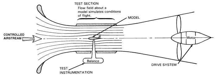
Wind Tunnel basics
The heart of the wind tunnel is the test section where a scale model is supported in a carefully controlled airstream that produces a flow of air about the model that duplicates the full-scale aircraft. Appropriate balances and test instrumentation measure the aerodynamic characteristics of the model and the field around it (its flow field). Although the form of a wind tunnel can vary, all wind tunnels have a drive system, a test section, use a model that is supported in an airstream and whose characteristics are measured by test instrumentation. The wind tunnel allows the aerodynamic forces of lift, drag, and side force in reference to the tunnel axis (the axial centerline of the test section) to be measured.
Spring Balance and Clinometer
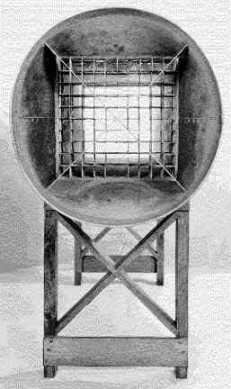
In a letter dated October 24, 1901, Wilbur explained to Octave Chanute how the lift balance he and Orville had designed would work. Wilbur’s diagram of the lift balance shows the lower arms of the balance, whereas the upper arms and the air foil are left to your imagination: "The arms ac bear the crosspiece aa and with the imaginary line cc form a parallelogram with the corners cc fixed and the arms ac turning on these points. The wind strikes the [drag fingers] (indicated by the short black lines) at an angle of 90 degrees in all positions of arms ac. Now if the lift [generated by an air foil on the upper arms is] transmitted to the point a and applied at right angles to arms ac, the [drag fingers] will [move] to the position indicated by the dotted lines and the pressure exerted will be as ax is to ay, i.e. the lift will be equal to the sine of the angle aca."
Replica of Wright Brothers' - Lift Balance
FINDING THE RIGHT FORMULA
To understand the difficulty of the problem the Wrights faced in September 1901 and the genius it took to solve it, you need to understand the mathematics behind the pine box and the used hacksaw blades that made up the tunnel and balances. If you are one of the mathematically challenged, don't despair - the logic behind the formulae is easy to grasp. In fact, you may have an advantage over someone educated in aeronautics. The methods used to analyze lift and drag today are different from what the Wright brothers used. Modern aeronautics looks at the forces in play on a wing as vectors. The Wright brothers and their contemporaries thought in terms of angles. Today, we use a form of calculus called vector analysis to study these forces; the Wright brothers used simple trigonometry Because of this, contemporary aeronautical engineers often react by labeling these older methods as wrong or incomplete. In their historical context, however, they were the best methods available at the time.
This isn't to say that the Wright's analysis of lift and drag was simplistic. In a letter to Octave Chanute on January 5, 1902, Wilbur carefully defines the forces in play on a wing in flight, taking into account the angle of attack (which he refers to as the angle of incidence), the path of flight, and the wind relative to the motion of the aircraft. "It has been a problem for me, ever since we began our experiments...what pressures we should attempt to measure and what should be the basis of our table." He wisely decides to make those measurements that will be most useful to him in analyzing actual flights. "...true lift and true drift...are alone to be considered in calculating glides." True lift Wilbur defines as the pressure or force directly opposed to gravity and true drift is a force perpendicular to it - what we now call drag.
Lilienthal's tables, he notes, do not contain numbers that are immediately useful. Lilienthal based his table on the pressure perpendicular to the chord (the normal force) and the portion of that pressure that increases or retards the forward motion of the aircraft (the tangential force) Neither could be used directly to design an airplane. "...normal and tangential [must be reduced] into vertical and horizontal components, which is inconvenient and a waste of time," Wilbur wrote. It was a bold -- maybe even brash -- statement. Lilienthal's astounding success as a glider designer and pilot in the 1890s had made his scientific writings central to aeronautics.
His emphasis on the tangential had led many investigators to conclude it was the key to soaring flight.But just five months after applying these tables incorrectly to the design of their 1901 glider, Wilbur now understands Lilienthal's tables and their limitations. The tangential, he knows, is a red herring. The Wright brothers will measure lift and drift. By doing so, they accomplished in a few months what had eluded other scientists for a century.
The brothers looked on these forces of lift and drift as the legs of a right triangle. This was the same triangle that Sir George Cayley drew in 1799 when he first conceived of the idea of a fixed-wing aircraft. Drift (or drag) was the base, lift was the side. According to the Pythagorean theorem that was drilled into most of us in high school, all the parts of that triangle -- base, side, hypotenuse, and the angles between them -- bear a distinct mathematical relationship to one another. By using simple trigonometry and ratios called sines, cosines, and tangents, the Wrights could find any part of the lift-drag triangle as long as they knew the magnitude of one part and one of the angles between the hypotenuse and another part.
They had used trigonometry to measure the performance of their glider when they flew them in Kitty Hawk. The brothers tied off the controls and flew each of the gliders as kites, attaching tether ropes to the leading outboard struts. The tether ropes, they noticed, stretched up at an angle. This angle was the result of lift and drag. The lower the lift or the higher the drag, the greater the angle of the rope as measured from the vertical. The rope was, in effect, the hypotenuse of the lift-drag triangle. Using an ordinary spring scale, they measured the tension on the ropes - this gave them a magnitude for the hypotenuse. They measured the angle with a clinometer, a surveyor's instrument given to them by Chanute. This allowed them to reduce the tension on the tether ropes into the forces of lift and drag using a few simple trig formulas:
Once they had found these numbers for lift and drag, the Wright brothers plugged them into established formulae to determine whether their wings were developing the expected lift and drag. These lift and drag formulae had their beginnings in the work of John Smeaton, an English engineer that studied the action of water wheels and windmills. Smeaton observed that when the wind blew against a sail, energy was transferred in the form of pressure on the sail. The amount of pressure generated was proportional to the size of the sail and the velocity of the wind. Smeaton multiplied the surface area times the square of the wind velocity, then devised a multiplier to convert the result into pressure. This multiplier became known as the coefficient of pressure or "Smeaton's coefficient". Smeaton published this formula in 1759:
MASSACHUSETTS INSTITUTE OF TECHNOLOGY
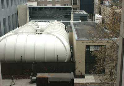
MIT'S 'WRIGHT BROTHERS' WIND TUNNEL
For more than a century, Massachusetts Institute of Technology wind tunnels have proven instrumental tools in the examination of aerospace, architectural, vehicular, sports and other engineering systems.
MIT's Wright Brothers Wind Tunnel's primary use is for student projects, research and instruction, however it is also available for commercial research and development. The tunnel can be operated between 0.25 atmospheres and 20 atmospheres, making it the only non-government pressurized wind tunnel in the United States. (Note that the test section is not isolated from the main tunnel, so during non-atmospheric operations the entire tunnel must be pumped or evacuated to make model changes, rendering this particular operation inefficient in terms of data points per hour.)
In addition to the usual force and moment balance system, this 7 X 10-foot elliptical cross-section wind tunnel has the necessary auxiliary equipment for inlet and diffuser testing, gust generation, and production of thick boundary layers to model the earth's boundary layer. It should be noted that the test section is not isolated from the main tunnel: during non-atmospheric operration the entire tunnel must be pumped or evacuated to make model changes, rendering the operation inefficient in terms of data points per hour.
Contact MIT : For Wind Tunnel information, including availability: wbwt@mit.edu
INVENTORS A - Z
The ultimate Robot Boat. Solarnavigator uses an advanced SWASSH hull as the platform to mount the world's first autonomous circumnavigation. A successful expedition could pave the way for improved safety at sea.
|
|||
|
This website is copyright © 1991- 2013 Electrick Publications. All rights reserved. The bird logo and names Solar Navigator and Blueplanet Ecostar are trademarks ™. The Blueplanet vehicle configuration is registered ®. All other trademarks hereby acknowledged and please note that this project should not be confused with the Australian: 'World Solar Challenge'™which is a superb road vehicle endurance race from Darwin to Adelaide. Max Energy Limited is an educational charity working hard to promote world peace.
|
|||
|
AUTOMOTIVE | BLUEPLANET BE3 | ELECTRIC CARS | ELECTRIC CYCLES | SOLAR CARS | SOLARNAVIGATOR |