|
WIND TURBINES EXPLAINED
|
|||||||||||||||||||||||||||||||||||||||||||||||||||||||||||||||||
|
A wind turbine is a machine for converting the kinetic energy in wind into mechanical energy. If the mechanical energy is used directly by machinery, such as a pump or grinding stones, the machine is usually called a windmill. If the mechanical energy is then converted to electricity, the machine is called a wind generator.
This article discusses the conversion machinery. See the broader article on wind power for more on turbine placement and controversy, and in particular see the wind energy section of that article for an understanding of the temporal distribution of wind energy and how that affects wind turbine design.
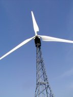
Tall tower holds turbine aloft where winds are stronger
For a machine that generates wind, see wind machine. For an unusual way to induce a voltage using an aerosol of ionised water, see vaneless ion wind generator.
Types of wind turbines
There are many types of wind turbines. They can be separated into two general types based on the axis about which the turbine rotates. Turbines that rotate around a horizontal axis are most common.
Additionally, we can also distinguish between wind turbines on the location in which they are to be used. Onshore, offshore, or even aerial wind turbines have unique design characteristics which are explained in more detail in the section on Turbine design and construction.
Wind turbines can also be used in conjuction with a solar power tower to extract the energy due to air heated by the Sun and rising thorugh a large vertical solar chimney. The first commercial solar power tower of this type is in the early stages of construction in Australia.
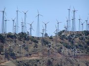
Wind farm in the Tehachapi Mountains, California
Horizontal axis
All existing HAWTs (or Horizontal Axis Wind Turbine) have the main rotor shaft and generator at the top of a tower, and must be pointed into the wind by some means. Small turbines are pointed by a simple wind vane, while large turbines generally use a wind sensor coupled with a servomotor. Most have a gearbox too, which turns the slow rotation of the blades into a quicker rotation that is more suitable for generating electricity.
Since a tower produces turbulence behind it, the turbine is usually pointed upwind of the tower. Turbine blades are made stiff to prevent the blades from being pushed into the tower by high winds. Additionally, the blades are placed a considerable distance in front of the tower and are sometimes tilted up a small amount.
Downwind machines have been built, despite the problem of turbulence, because they don't need an additional mechanism for keeping them in line with the wind, and because in high winds, the blades can be allowed to bend which reduces their swept area and thus their wind resistance. Because turbulence leads to fatigue failures and reliability is so important, most HAWTs are upwind machines.
There are several types of HAWT.
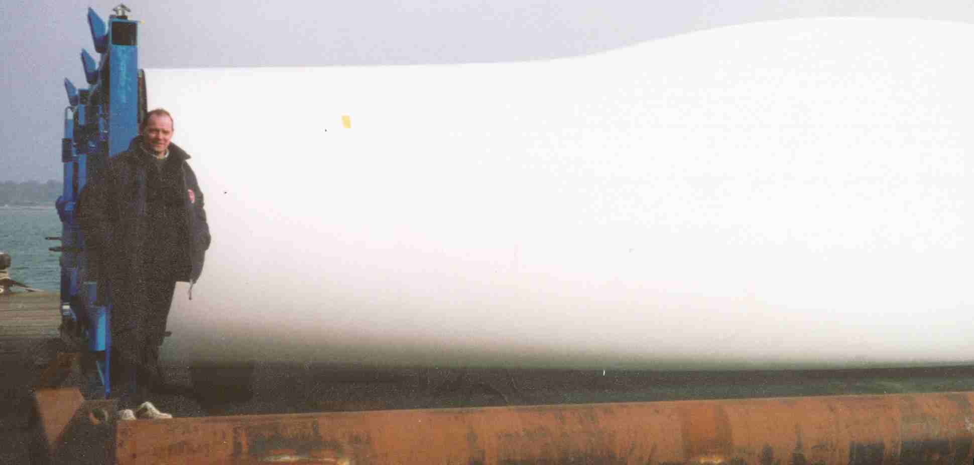
Nelson Kruschandl and turbine blade Southampton
Counter-rotating horizontal axis turbines
Counter rotating turbines can be used to increase the rotation speed of the electrical generator. When the counter rotating turbines are on the same side of the tower, the blades on the one in front are angled forwards slightly so as to never hit the rear ones. They are either both geared to the same generator or, more often, one is connected to the rotor and the other to the field windings. Counter rotating turbines geared to the same generator have additional gearing losses. Counter rotating turbines connected to the rotor and stator are mechanically simpler; but, the field windings need slip rings which adds complexity, wastes some electricity and wastes some mechanical power. As of 2005, no large practical counter-rotating HAWTs are commercially sold.
Counter rotating turbines can be on opposite sides of the tower. In this case it is best that the one at the back be smaller than the one at the front and set to stall at a higher wind speed. This way, at low wind speeds, both turn and the generator taps the maximum proportion of the wind's power. At intermediate speeds, the front turbine stalls; but, the rear one keeps turning, so the wind generator has a smaller wind resistance and the tower can still support the generator. At high wind speeds both turbines stall, the wind resistance is at a minimum and the tower can still support the generator. This allows the generator to function at a wider wind speed range than a single-turbine generator for a given tower.
To reduce sympathetic vibrations, the two turbines should turn at speeds with few common factors, for example 7:3 speed ratio. Overall, this is a more complicated design than the single-turbine wind generator, but it taps more of the wind's energy at a wider range of wind speeds.
Cyclic stresses and vibration
Cyclic stresses fatigue the blade, axle and bearing material, and were a major cause of turbine failure for many years. The principle advantage of a horizontal over a vertical rotation axis is much lower cycling stresses, but even so, HAWTs endure significant cyclic stresses which strongly affect their design.
Because wind velocity increases at higher altitudes, the backward force and torque on a horizontal axis wind turbine (HAWT) blade peaks as it turns through the highest point in its circle. The tower hinders the airflow at the lowest point in the circle, which produces a local dip in force and torque. These two effects combine to produce a cyclic twist on the main bearings of a HAWT. The combined twist is worst in machines with an even number of blades, where one is straight up when another is straight down. To improve reliability, teetering hubs are used which allow the main shaft to rock through a few degrees, so that the main bearings do not have to resist the torque peaks.
When the turbine turns to face the wind, the rotating blades act like a gyroscope. As it pivots, gyroscopic precession tries to twist the turbine into a forward or backward somersault. For each blade on a wind generator's turbine, precessive force is at a minimum when the blade is horizontal and at a maximum when the blade is vertical. This cyclic twisting can quickly fatigue and crack the blade roots, hub and axle of the turbine.
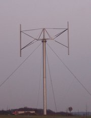
'H' Darrieus turbine blades
Vertical axis
Vertical axis turbines (or VAWTs) have the main rotor shaft running vertically. The main advantages of this arrangement are that the generator and/or gearbox can be placed at the bottom, on or near the ground, so the tower doesn't need to support it, and the fact that the turbine doesn't need to be pointed into the wind. Drawbacks are usually the pulsating torque produced during each revolution, and the difficulty of mounting vertical axis turbines on towers. This means they must operate in the slower, more turbulent air flow near the ground, with lower energy extraction efficiency.
Offshore
Offshore wind turbines are considered to be less obtrusive than turbines on land, as their apparent size and noise can be mitigated by distance. Because water has less surface roughness than land, the average wind speed is usually higher over open water. This allows offshore turbines to use shorter towers, making them less visible. In stormy areas with extended shallow continental shelves (such as Denmark), turbines are practical to install, and give good service - Denmark's wind generation provides about 12-15% of total electricity demand in the country, with many offshore windfarms. Denmark plans to increase wind energy's contribution to as much as half of its electrical supply.
The offshore environment is, however, more expensive. Offshore towers are generally taller than onshore towers once one includes the submerged height, and offshore foundations are generally more difficult to build and more expensive as well. Power transmission from offshore turbines is generally through undersea cable, which is far more expensive to install than cables on land and requires high voltage direct current operation if significant distance is to be covered - which then requires yet more equipment. The offshore environment is also corrosive and abbrasive. Repairs and maintenance are much more difficult, and much more costly than on onshore turbines. Offshore wind turbines are outfitted with extensive corrosion protection measures like coatings and cathodic protection.
While there is a significant market for small land-based windmills, offshore wind turbines have recently been and will probably continue to be the largest wind turbines in operation, because larger turbines reduce the marginal cost of many of the difficulties of offshore operation. There are some conceptual designs that might make use of the unique offshore environment. For example, a floating turbine might orient itself downwind of its anchor, and thus avoid the need for a yawing mechanism. One concept for offshore turbines has them generate rain, instead of electricity. The turbines would create a fine aerosol, which is envisioned to increase evaporation and induce rainfall, hopefully on land.
Aerial
Winds at a height of a few kilometres are quite constant and very fast (often over 40 m/s). Theoretically, flying wind turbines could tap into the energy in these winds. One design has four turbines linked together forming a kind of kite. Winds keep the construction in the air, while causing the blades on the turbines to rotate. The kite wire would carry the electrical energy to the ground. This approach would require no-fly-zones around the deployment site, and might require electrical energy to remain aloft if the winds would ever die down.
Turbine design and construction
Tower height
The wind blows faster at higher altitudes because of the drag of the surface (sea or land) and the viscosity of the air. The variation in velocity with altitude, called wind shear is most dramatic near the surface. Typically, the variation follows the 1/7th power law, which predicts that wind speed rises proportionally to the seventh root of altitude. Doubling the altitude of a turbine, then, increases the expected wind speeds by 10% and the expected power by 34%. Doubling the tower height generally requires doubling the diameter as well, increasing the amount of material by a factor of eight.
For HAWTs, tower heights approximately twice the blade length have been found to balance material costs of the tower against better utilisation of the more expensive active components.
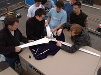
Small HAWT ship three separate bladed turbines for onsite assembly to central hub
Number of blades
Although turbines can be built with any number of blades, there are many constraints. There are a number of vibration modes that increase in peak intensity as the number of blades decreases. Some of these vibrations, besides causing wear on the machine, are also audible. Thus, noise and wear considerations point to larger numbers of blades, generally at least 3.
Many small scale wind turbines, such as the Whisper 175, use 2 blades because such turbines are easy to construct as they avoid the need for using a hub with linkages to individual blades, and the blade(s) can be shipped easily in one long package. Three-bladed turbines, which are much more efficient, and more quiet, require more complicated onsite assembly.
Turbines with larger numbers of smaller blades operate at a lower Reynolds number and are therefore less efficient. Small turbines with 4 or more blades suffer further losses as each blade operates partly in the wake of the other blades. Also, the cost of the turbine usually increases with the number of blades. Most wind turbines have three blades.
Rotation control
Tip speed ratio = the ratio between the speed of the wind and the speed of the tips of the blades of a wind turbine.
Modern wind turbines are designed to spin at varying speeds (a consequence of their generator design, see below). Use of aluminum and composites in their blades has contributed to low rotational inertia, which means that newer wind turbines can accelerate quickly if the winds pick up, keeping the tip speed ratio more nearly constant. Operating closer to their optimal tip speed ratio during energetic gusts of wind allows wind turbines to improve energy capture from sudden gusts that are typical in urban settings.
In contrast, older style wind turbines were designed with heavier steel blades, which have higher inertia, and rotated at speeds governed by the AC frequency of the power lines. The high inertia buffered the changes in rotation speed and thus made power output more stable. The speed at which wind turbines rotate must be controlled for several reasons:
Because the power of the wind increases as the cube of the speed wind, turbines have to be built to survive much higher wind loads (such as gusts of wind) than those from which they can practically generate power. Since the blades generate more downwind force (and thus put far greater strain on the tower) when they are producing torque, most wind turbines have ways of slowing rotation in high winds. Overspeed control is exerted in two main ways: aerodynamic stalling or furling, and mechanical braking. Furling is the preferred method of slowing wind turbines.
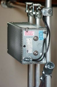
Dynamic braking resistor for wind turbine
Stalling and furling
Stalling works by increasing the angle at which the relative wind strikes the blades (angle of attack), and it reduces the induced drag (drag associated with lift). Stalling is simple because it can be made to happen passively (it increases automatically when the winds speed up), but it increases the cross-section of the blade face-on to the wind, and thus the ordinary drag. A fully stalled turbine blade, when stopped, has the flat side of the blade facing directly into the wind. Furling works by decreasing the angle of attack, which reduces the induced drag from the lift of the rotor, as well as the cross-section. One major problem in designing wind turbines is getting the blades to stall or furl quickly enough should a gust of wind cause sudden acceleration. A fully furled turbine blade, when stopped, has the edge of the blade facing into the wind.
A fixed-speed HAWT inherently increases its angle of attack at higher wind speed as the blades speed up. A natural strategy, then, is to allow the blade to stall when the wind speed increases. This technique was used on many early HAWTs, until it was realised that stalled blades generate a large amount of vibration (noise). Standard modern turbines all furl the blades in high winds. Since furling requires acting against the torque on the blade, it requires active (usually hydraulic) pitch angle control which is only cost-effective on very large turbines. These systems are usually spring loaded, so that if hydraulic power fails, the blades automatically furl. Electromagnetic braking
Braking of a turbine can also be done by dumping energy from the generator into a resistor bank, converting the kinetic energy of the turbine rotation into heat. This method is useful if the connected load on the generator is suddenly reduced or is too small to keep the turbine speed within its allowed limit. Cyclically braking causes the blades to slow down, which increases the stalling effect, reducing the efficiency of the blades. This way, the turbine's rotation can be kept at a safe speed in faster winds while maintaining (nominal) power output.
Mechanical braking
A mechanical drum brake or disk brake is used to hold the turbine at rest for maintenance. Such brakes are usually applied only after blade furling and electromagnetic braking have reduced the turbine speed, as the mechanical brakes would wear quickly if used to stop the turbine from full speed.
Construction and maintenance costs are similar for large and small turbines, so utility companies build the largest feasible turbines.
Turbine size
For a given survivable wind speed, the mass of a turbine is approximately proportional to the cube of its blade-length. Wind power intercepted by the turbine is proportional to the square of its blade-length. The maximum blade-length of a turbine is limited by both the strength and stiffness of its material.
Labor and maintenance costs increase only gradually with increasing turbine size, so to minimize costs, wind farm turbines are basically limited by the strength of materials, and siting requirements.
Generating electricity
Wind turbines generate electricity, using an electrical generator. Moving a conductor through a magnetic field will develop a voltage across the conductor.
For large, commercial size horizontal-axis wind turbines, the generator is mounted in a nacelle at the top of a tower, behind the hub of the turbine rotor. Depending on the manufacturer, a speed increasing gear box may be inserted between the rotor hub and the generator, so that the generator cost and weight can be reduced. In a vertical-axis wind turbine the heavy generator and gearbox can be mounted near the ground, which makes maintenance easier and reduces some components of structural cost; but these advantages do not offset the torque-ripple-induced reliability disadvantage of vertical-axis turbines, and so they are not used for commercial electric power production.
Commercial size generators have a rotor carrying a field winding so that a rotating magnetic field is produced inside a set of windings called the stator. While the rotating field winding consumes a few per cent of the generator output, adjustment of the field current allows good control over the generator output voltage. Very small wind generators (a few watts to perhaps a kilowatt in output) may use permanent magnets but these are too costly to use in large machines and do not allow convenient regulation of the generator voltage.
Wind turbines on Solar Navigator (test rig model)
Electrical generators inherently produce AC power, as the voltage changes direction (from positive to negative) whenever the poles of the magnet switch places. Older style wind generators rotate at a constant speed, to match power line frequency (60 Hz in North America, 50 Hz in most of the rest of the world), which allowed the use of less costly induction generators. Newer wind turbines often turn at whatever speed generates electricity most efficiently. The variable frequency current is then converted to DC and then back to AC matching the line frequency and voltage. Although the two conversions require costly equipment and cause power loss, the turbine can capture a significantly larger amount of the wind power.
In some cases, especially when turbines are sited offshore, the DC energy will be transmitted from the turbine to a central (onshore) inverter for connection to the grid. Materials
One of the best construction materials available (in 2001) is graphite-fibre in epoxy. Graphite composites can be used to build turbines of sixty meters radius, enough to tap a few megawatts of power. Smaller household turbines can be made of lightweight fiberglass, aluminum, or sometimes laminated wood.
Wood and canvas sails were originally used on early windmills. Unfortunately they require much maintenance over their service life. Also, they have a relatively high drag (low aerodynamic efficiency) for the force they capture. For these reasons they were superseded with solid airfoils.
Accidents
Accidents with wind turbines are not rare. However in most cases no people were injured and killed and so they are often not reported, however they give often a spectacular appearance. The most frequent accidents reasons are burns and lost wings. Sometimes there were also total crashes.
History
Wind machines were used for grinding grain in Persia as early as 200 B.C. This type of machine spread throughout the Islamic world and were introduced by Crusaders into Europe in the 13th century. Windmills have been used to grind grain since around the 10th century, but they do not generate electricity. By the 14th century Dutch windmills were in use to drain areas of the Rhine River delta. Wind turbines, machines that harness the energy of the wind to generate electrical energy, were first invented in the 19th century in Denmark.In Denmark by 1900 there were about 2500 windmills for mechanical loads such as pumps and mills, producing an estimated combined peak power of about 30 MW. The first windmill for electricity production was built in Denmark in 1890, and in 1908 there were 72 wind-driven electric generators from 5 kW to 25 kW. The largest machines were on 24 m towers with four-bladed 23 m diameter rotors.
By the 1930s windmills were mainly used to generate electricity on farms, mostly in the United States where distribution systems had not yet been installed. In this period, high tensile steel was cheap, and windmills were placed atop prefabricated open steel lattice towers. A forerunner of modern horizontal-axis wind generators was in service at Yalta, USSR in 1931. This was a 100 kW generator on a 30 m tower, connected to the local 6.3 kV distribution system. It was reported to have an annual load factor of 32 per cent, not much different from current wind machines.
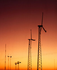
High-efficiency wind turbines (foreground) v traditional windmills (background)
In 1941 the world's first megawatt-size wind turbine was connected to the local electrical distribution system at Grandpa's Knob, Vermont, USA. This 1.25 MW Smith-Putnam turbine operated for 1100 hours before a blade failed at a known weak point, which had not been reinforced due to war-time material shortages. In the 1940s, the U.S. had a rural electrification project that killed the natural market for wind-generated power, since network power distribution provided a farm with more dependable usable energy for a given amount of capital investment.
In the 1970s many people began to desire a self-sufficient life-style. Solar cells were too expensive for small-scale electrical generation, so practical people turned to windmills. At first they built ad-hoc designs using wood and automobile parts. Most people discovered that a reliable wind generator is a moderately complex engineering project, well beyond the ability of most romantics. Practical people began to search for and rebuild farm wind-generators from the 1930s. Jacobs wind generators were especially sought after.
Later, in the 1980s, California provided tax rebates for ecologically harmless power. These rebates funded the first major use of wind power for utility electricity. These machines, gathered in large wind parks such as at Altamont Pass would be considered small and un-economic by modern wind power development standards.
As aesthetics and durability became more important, turbines were placed atop steel or reinforced concrete towers. Small generators are connected to the tower on the ground, then the tower is raised into position. Larger generators are hoisted into position atop the tower and there is a ladder or staircase inside the tower to allow technicians to reach and maintain the generator. Originally wind generators were built right next to where their power was needed.
With the availability of long distance electric power transmission, wind generators are now often on wind farms in windy locations and huge ones are being built offshore, sometimes transmitting power back to land using high voltage submarine cable. Since wind turbines are a renewable means of generating electricity, they are being widely deployed, but their cost is often subsidised by taxpayers, either directly or through renewable energy credits. Much depends on the cost of alternative sources of electricity. Wind generator cost per unit power has been decreasing by about four percent per year.
World market for wind energy plants in 2003
Companies in wind turbine industry
See also
LINKS
Primarily technical:
Business associations:
Other:
References
MORE USEFUL LINKS
British Wind Energy Assoc (BWEA) European Wind Energy Assoc (EWEA) Assoc of British Offshore Ind (ABOI) Danish Wind Turbine Manufacturers Assoc Energy Technology Support Unit (ETSU) Office of Science and Tech (OST) Eng & Physical Sciences R Council (EPSRC) Natural Environment R Council (NERC) Central Lab of R Councils (CLRC) Euro Community R & D Inf Service (CORDIS) Institute of Mechanical Engineers (IMechE) Institution of Electrical Engineers (IEE)
HOW DOES SOLAR NAVIGATOR BENEFIT FROM WIND TURBINES ?
HOW
CAN A BOAT
BENEFIT FROM WIND TURBINES ?
Bluefish
Robot Boat Front Elevation 2013
You
can see from the drawing above that the Bluefish ZCC (Bluebird Marine Systems
Ltd) has four mini wind
turbines, each of which generates 1.5Kw to provide enough energy
to run the integrated autonomous hardware. With research projects such as
this, the equipment is bulky and relatively energy hungry, but with each
refinement the controlling chips, software and mechanical end effectors become
smaller and more efficient. SolarNavigator
was the first (proposed) autonomous vessel to harness wind energy in this
way, but the Bluefish ZCC development programme (again a proposed
development of GB1301488) has taken this a stage further with up to
40kW wind turbines onboard for a civilian vessel and 80kW for military
variants. You can
read more about how the system works on their pages by clicking on the
pictures above and below.
Bluefish
Robot Boat
|
|||||||||||||||||||||||||||||||||||||||||||||||||||||||||||||||||
|
|||||||||||||||||||||||||||||||||||||||||||||||||||||||||||||||||