|
STIRLING ENGINE |
|||
|
HOME SITE INDEX CATAMARAN HULL SOLAR PANELS ELECTRIC MOTORS BATTERIES EXPEDITION SPONSORS |
|||
|
The Stirling engine, also known as the hot air engine, is a heat engine of the external combustion piston engine type whose heat-exchange process allows for near-ideal efficiency in conversion of heat into mechanical movement by following the Carnot cycle as closely as is practically possible with given materials.
Its invention is credited to the Scottish clergyman Rev. Robert Stirling in 1816 who made significant improvements to earlier designs and took out the first patent. He was later assisted in its development by his engineer brother James Stirling. General description
The inventors sought to create a safer alternative to the steam engines of the time, whose boilers often exploded due to the high pressure of the steam and the inadequate materials. Stirling engines will convert any temperature difference directly into movement.
The Stirling engine works by the repeated heating and cooling of a sealed amount of working gas, usually air or other gases such as hydrogen or helium. The gas follows the behaviour described by the gas laws which describe how a gas' pressure, temperature and volume are related. When the gas is heated, because it is in a sealed chamber, the pressure rises and this then acts on the power piston to produce a power stroke.
When the gas is cooled the pressure drops and this means that less work needs to be done by the piston to recompress the gas on the return stroke, giving a net gain in power available on the shaft. The working gas flows cyclically between the hot and cold heat exchangers.
The working gas is sealed within the piston cylinders, so there is no exhaust gas, (other than that incidental to heat production if combustion is used as the heat source). No valves are required, unlike other types of piston engines.
Engine
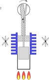
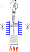
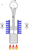
Some Stirling engines use a separate displacer piston to move the working gas back and forth between cold and hot reservoirs. Others rely on interconnecting the power pistons of multiple cylinders to move the working gas, with the cylinders held at different temperatures.
In true Stirling engines a regenerator, typically a mass of wire, is located between the reservoirs. As the gas cycles between the hot and cold sides, its heat is transferred to and from the regenerator. In some designs, the displacer piston is itself the regenerator. This regenerator contributes to the efficiency of the Stirling cycle.
The ideal Stirling engine cycle has the same theoretical efficiency as a Carnot heat engine for the same input and output temperatures. The thermodynamic efficiency is higher than steam engines (or even some modern internal combustion and Diesel engines).
Stirling cryocoolers
Stirling engines will also work in reverse: when applying motion to the shaft, a temperature difference appears between the reservoirs. One of their modern uses is in refrigeration and cryogenics. The first Stirling-cycle cryocooler was developed at Philips in the 1950s and commercialized in such places as liquid nitrogen production plants. The Philips Cryogenics business evolved until it was split off in 1990 to form the Stirling Cryogenics & Refrigeration BV, Stirling The Netherlands. This company is still active in the development and manufacturing Stirling cryocoolers and cryogenic cooling systems.
A wide variety of smaller size Stirling cryocoolers are commercially available for tasks such as the cooling of sensors.
Configurations
Engineers classify Stirling engines into three distinct types:
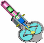
Rhombic Drive Beta Stirling Design
Changes to the configuration of mechanical Stirling engine continues to interest engineers and inventors alike. Notably, some are in hot pursuit of the rotary Stirling engine; the goal is to convert power from the Stirling cycle directly into torque, a similar goal to that of the design of the rotary combustion engine.
There is also a field of "Free piston" stirling cycles engines, including those with liquid pistons and those with diaphrams as pistons. [See the book "Free Piston Stirling Cycle Engines" by G. Walker]
An alternative to the mechanical Stirling engine is the fluidyne pump, which uses the Stirling cycle via a hydraulic piston. In its most basic form it contains a working gas, a liquid and two check valves for moving parts. The work produced by the fluidyne goes into pumping the liquid.
Heat sourcesAny temperature difference will power a Stirling engine and the term "external combustion engine" often applied to it is misleading. A heat source may be the result of combustion but can also be solar, geothermal , or nuclear. Likewise a "cold source" below the ambient temperature can be used as the temperature difference. A cold source may be the result of a cryogenic fluid or iced water. Since small differential temperatures require large mass flows, parasitic losses in pumping the heating or cooling fluids rise and tend to reduce the efficiency of the cycle.
Because a heat exchanger separates the working gas from the heat source, a wide range of combustion fuels can be used, or the engine can be adapted to run on waste heat from some other process. Since the combustion products do not contact the internal moving parts of the engine, a Stirling engine can run on landfill gas containing siloxanes without the accumulation of silica that damages internal combustion engines running on this fuel. The life of lubricating oil is longer than for internal-combustion engines.
Strengths of Stirling engines
Problems with Stirling engines
History and development
Devices called air engines have been recorded from as early as 1699 around the time when the laws of gasses were first set out. The English inventor Sir George Caley is known to have devised air engines c. 1807. Robert Stirling's innovative contribution of 1816 was what he called the 'Economiser' now known as the regenerator which acts to retain heat in the hot portion of the engine as the air passes to the cold part and thus improve the efficiency.
During the nineteenth century the Stirling engine found applications anywhere a source of low to medium power was required , a role that was eventually usurped by the electric motor at the century's end.
It was also employed in reverse as a heat pump to produce early refrigeration.
In the late 1940s the Philips Electronics company in The Netherlands were searching for a versatile electricity generator to enable worldwide expansion of sales of its electronic devices in areas with no reliable electricity infrastructure. The company put a huge R&D research effort into Stirling engines building on research it had started in the 1930s and which lasted until the 1970s. The only lasting commercial spin-off from this for Philips was its reversed Stirling engine: the Stirling cryocooler.
Kockums[5], the Swedish shipbuilder, had built at least 10 commercially successful Stirling powered submarines during the 1980s. As of 2005 they have started to carry compressed oxygen with them. (No endurance stated.)
On August 11, 2005, Southern California Edison announced an agreement to purchase solar powered Stirling engines from Stirling Energy Systems over a twenty year period and in quantity (20,000 units) sufficient to generate 500 megawatts of electricity. These systems - to be installed on a 4,500 acre (19 km²) solar farm - will use mirrors to direct and concentrate sunlight onto the engines which will in turn drive generators.
LINKS:How it works
HistoryAcademic and technical studies
PatentsSocieties and conferencesHobbyists and enthusiasts
Professional manufacturers
|
|||
|


