|
|
|||||||||||||||||||||||||||||||||||||||||||
|
HOME | BIOLOGY | FILMS | GEOGRAPHY | HISTORY | INDEX | INVESTORS | MUSIC | NEWS | SOLAR BOATS | SPORT |
|||||||||||||||||||||||||||||||||||||||||||
|
Boat design is a compromise. So too is rudder design. If Solar Navigator is to glide through the water using minimal energy, her rudders should induce the least possible drag. Unfortunately, she must be able to manouevre in harbour also, hence sufficient area to generate additional turning force increases drag.
BASIC CONCEPTS
"Foil" is the common term that applies to wings, rudders, keels and centerboards. To the aerodynamicist and hydrodynamicist they are all the same. A basic concept of fluid mechanics is Reynolds number.
If two different situations have the same Reynold's numbers the fluid flow will be the same. This allows one to take results for airplane wings and apply them for center boards and rudders provided the Reynold's number is the same.
If the Reynold's Numbers for two different situations are not the same, one can not make valid predictions of the fluid flow. It may be the similar, or it may be very different. Later there will be different suggestions applicable to the size and typical speed of different boats.
Angle of attack (AOA) is the small angle a boat has relative to its flow through the water. If you are sailing straight down wind, the AOA of the centerboard or keel will be 0. Pinching into the wind with a lot of leeway will result in a high AOA. The AOA of the rudder naturally depends on what the helmsman is doing.
Drag is the force parallel to the oncoming flow. Lift is the force perpendicular to the flow. Generally speaking, drag tends to slow the boat. Lift on the rudder is how it turns the boat. Lift on a centerboard or keel is what makes it possible to sail up wind.
All of the above are interdependent. For a well designed symmetrical foil, when AOA is 0, lift is 0 and drag is small. As AOA increases, lift and drag both tend to increase. At a certain AOA, lift will reach a maximum, and drag goes up rapidly. This is called the stall angle. Note that the hull also generates lift and drag which will effect the total performance of the boat. In a sail boat the flow of air over the sails also stalls if the AOA of the sail gets too high. This is the fluid dynamics explanation behind why you lose speed when you pinch into the wind.
Determining a "good" foil shape requires either experimental models or a rather large computer program to determine the lift and drag as a function of AOA for a variety of candidate shapes. Then repeat that process for a range of speeds. Final select a shape based on the expected conditions and your sailing style. The problem is just too complex to have a computer program that solves Newton's Laws of Motion and cranks out the "best" shape.
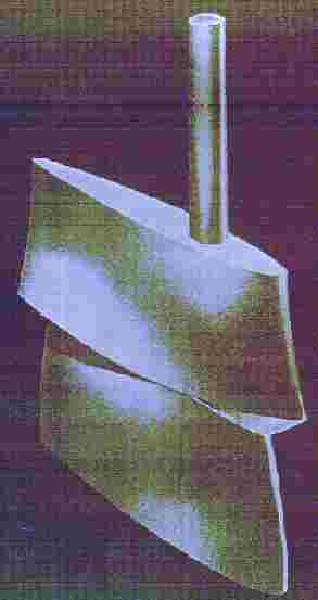
The Contraglide - Rudder by St. Louis Ship. Shaped very much like ordinary aircraft- Wings, with each section having a slightly different - shape. These rudders steer more "In One Particular Direction", depending upon which side of the hull - its designed to work upon, meaning there are Port & Starboard versions of the Contraglide. Used on Single / Twin & Triple Screw vessels, to cancel out a hulls tendency to constantly want to turn, or torque the boat in the same direction, as its props are turning. On a twin screw - for example, "If One Engine - Goes Down", a vessel equipped with these rudders can continue to steer a straight coarse, without constant pilot - corrections. So they cancel - prop/hull torque effect problems and save fuel and make it far easier to steer. But they're extremely - expensive to build, install and repair or maintain.
CROSS SECTION SHAPES
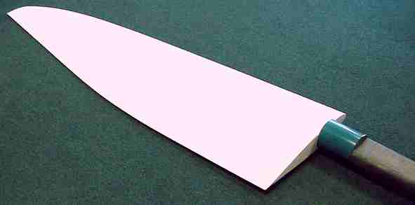
Shape for Most Boats - Many sail boats have foils based on NACA 4 digit airfoil design, which was defined in 1933 and based on a lot of trial and error by many people in the early years of aviation. Because it was based on small slow airplanes, the range of Reynold's numbers is similar to that of interest to sailors. Amazingly this design is still very good for boat foils, although some special exceptions are listed below. This shape is published in table form as NACA-00XX, where XX is the thickness expressed as a percentage of the chord. Harold Ginsberg has a shareware program, NACA4GEN, that will compute the shape and also generate computer files readable by other CAD programs. Here is the formula, if you wish to do your own computations:
NACA continued its work in developing better foil sections. The NACA 6 series has a region of lower drag for AOA of 1 or 2 degrees. It has been successfully used for airplane wings. Pollock compared the two shapes and concluded for the Reynold's Numbers that apply to most sail boats, the older NACA 00XX actually had less drag. If you are building one of the high performance ocean going trimarans, the 6-series might be a better choice. If are building a big high-performance boat, you can probably afford a consulting engineer to explore this issue.
Pollock also analyzed the effect of different thicknesses. Thinner foils have less drag, thicker foils have higher stall angle and greater maximum lift. He summarized his results as follows:
Thin Foils - Class rules also are a consideration. Tom Speer shared his results from a Fortran program known as "the Eppler Code" which he managed to fit onto his PC. Speer compared the performance of the NACA 00XX shape to the design that has been used on some acrobatic aircraft. The "Extra" section uses an elliptical shape for the leading portion of the foil and a straight wedge for the trailing portion. The formula for an ellipse is:
For 9 and 12 percent thicknesses, the NACA shape is clearly superior. For 6 percent, the Extra shape is predicted to have less drag. (I am considering building one of each shape.)
Parallel Sided Foils - Some classes specify the foils must have parallel sides with some amount of fairing of the edges allowed. Pollack first considered an elliptical shape for the leading edge. A fairing length about 2t gives good lift, but high drag. A fairing length of 4t gives low drag, but not much lift. He developed a new section which, for low speeds, is nearly as good as the NACA 0004 section.
The best would be Xle = 4 * t, but 2 * t wouldn't be all that bad if the class rules restrict it. The trailing edge fairing should be as long as possible, with the suggested shape:
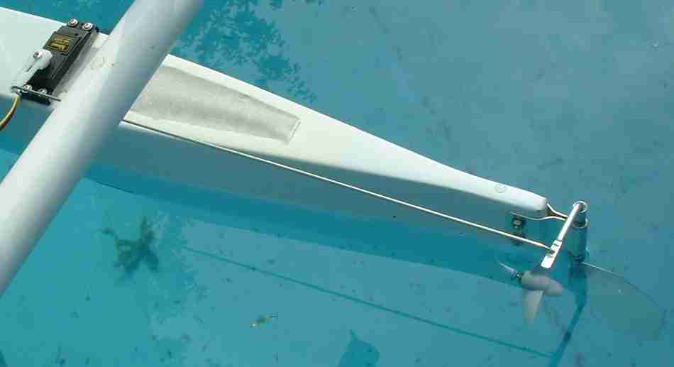
Even Thinner Foils - When the foil is really thin, it acts as a flat plate. There isn't much you can do to affect its performance. Analysis of even 6 per cent thickness shows much less sensitivity to shape than thicker foils. This is a limiting situation in model boats, such as the Solar Navigator development models as seen in the picture below. The edges are simply rounded so that they are safe to handle.
The Trailing Edge - All shapes ideally have an infinitely thin trailing edge. Practical considerations, like nicks and dings, require a minimum thickness. All of the people who have studied this agree that the best thing is to compute the shape as if the foil were to be slightly longer. Then cut it off at the desired thickness with the edges square.
PLAN FORM Plan form is the aerodynamicist's term for the side view of the foil. The preceding analysis of cross section only used a 2 dimensional view, but the real world is 3D. Near the bottom of a foil, the water may turn toward the bottom edge instead of going straight back and as a result produce less lift. This can be minimized by making the trailing edge vertical and not swept back. Pollack noted that while a "shark fin shape" might theoretically have less drag, he would,
The trailing corner should be kept square even if the class rules allow it to be rounded. Wings on the keels of some racing yachts and fins on the wing tips of new airliners help make the end portion of the foil more efficient.
Longer (deeper) foils will have a better lift to drag ratio, but also cause increased heeling because the lift is created further down. The length of the foil will be limited by some combination of class rules, frequency of running aground, and ability to keep the boat upright.
If the foil must be short, then use a rectangular plan form to get all the area you can. For longer foils there will be less drag for the same amount of lift if the leading edge is tapered back. Some designs have a straight leading edge with the length at the bottom from 40% to as little as 20% of the length at the top; others use an elliptical shape. Depending on the design criteria, either might be better. Obviously a straight edge will be easier to build.
KORT NOZZLES
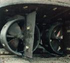
Kort Nozzles increase the efficiency of propellers on slower displacement vesels operating between 5 - 10 knots. The picture shows Kort nozzles mounted under a typical - Tugboat Hull. Note how the bottom = of each rudder, is mounted into a "Rudder Post or BRACE" .... attached to the back - of each Kort Nozzle. This is a typical fashion for many vessels = Tugs & Towboats and others, where space is limited and rudder brace points - are critical for added strength. And in many cases, the rudder itself, may actually set = slightly inside the kort nozzle, with just inches of space between it and the propeller.
CONSTRUCTION COMMENTS
Whatever material and technique you choose, to achieve the theoretical results of a computer you must be extremely precise when building a foil. Construct accurate templates. It is especially important to avoid any waviness or irregularity in the shape along either axis.
Here are some rather unusual techniques to consider: The following technique for wooden foils was suggested by Richard Engelbrecht- Wiggans. Compute the chord positions vs. thickness in 1/32 inch steps. Laminate an approximate shape from plywood and /or verniers. Use a belt sander to shape the board. If you do it right, the glue lines between the layers will be straight, and at the pre-computed positions. Since wood is too fragile to make the trailing edge of a foil very thin, he also suggested using factory-made fiberglass glazing. Cut two strips of fiberglass as long as the trailing edge and several inches wide. Lay the strips on top of each other, and tape them together along what will become the trailing edge. Make a fixture with the desired angle of the trailing edge to hold the strips. Mix up a batch of epoxy with thickener to glue the previously made wooden portion of the foil to the fiber glass.
The standard method for working with fiberglass requires first making a precision female mould. Strojnick suggests this technique sometimes used for making airplane wings. Lay up a skin of fiberglass on a piece of Plexiglas. When it has partially set, but not yet hard, peel it off the plastic and form it around a male mold for the final cure. This gives a very smooth finish without the difficulty of having to make your mold very smooth. His books go into much more detail.
Parker suggested:
Speer wrote:
A hot wire, such as that used for cutting styrofoam for packaging, may be useful. They are great for shaping the cores used for the fairings on axles (airfoil shaped to produce downforce and reduce heeling/skidding).
Rudders on Youtube
ACKNOWLEDGMENTS
What is posted here is a summary of input from those listed below.
Richard Engelbrect-Wiggans mailto:eplus17@uiuc.edu
FURTHER READING
The following books have been suggested some of which may be hard to find: Abbott and von Doenhoff, Theory of Wing Sections, Dover Publications, $13.95 US Bethwaite, Frank, High Performance Sailing, 1993, distributed by McGraw Hill. ISBN 0070057990 Larsson and Eliasson, Principles of Yacht Design Marchaj, Aero-Hydrodynamics of Sailing, Dodd, Mead & Co. Hoerner, Fluid Dynamic Drag, Fluid Dynamic Lift Strojnick, Laminar Aircraft Technologies, Laminar Aircraft Design, Laminar Aircraft Structures Two references for vacuum bagging which could be useful: Merrick, Gordon, Vacuum-Bag Veneering, Fine Woodworking Vol. 84, October, 1990 Square, David Shath, Basics of Vacuum-Bag Veneering, Fine_Woodworking Vol 109, December, 1994
(If you are at school: Ask your teacher about anything you are not clear on. Make the most of your time at school to find out about subjects that interest you. We welcome all input on technical subjects) SEE SOLARNAVIGATOR'S EARLY MODEL RUDDERS
The world's first ocean going robot ship. Solarnavigator is a SWASSH design, utilizing solar power for extended duration during a world autonomous navigation attempt set for 2015 - if all goes according to schedule.
+ 44 (0) 1323 831727 +44 (0) 7842 607865
Blueplanet Productions Solar House, BN27 1RF, United Kingdom
|
|||||||||||||||||||||||||||||||||||||||||||
|
This website is copyright © 1991- 2013 Electrick Publications. All rights reserved. The bird logo and names Solar Navigator and Blueplanet Ecostar are trademarks ™. The Blueplanet vehicle configuration is registered ®. All other trademarks hereby acknowledged and please note that this project should not be confused with the Australian: 'World Solar Challenge'™which is a superb road vehicle endurance race from Darwin to Adelaide. Max Energy Limited is an educational charity. |
|||||||||||||||||||||||||||||||||||||||||||
|
AUTOMOTIVE | ECOSTAR | ELECTRIC CARS | ELECTRIC CYCLES | SOLAR CARS |
|||||||||||||||||||||||||||||||||||||||||||