|
|
||
|
WHEN DESIGNING A SOLAR POWERED BOAT IT IS DOUBLY IMPORTANT TO SIZE THE PROPULSION SYSTEM. The major components that need to be considered are:
SIZING THE MOTOR(S)
To be able to size the motors we need to know the displacement of the vessel, the length and the hull shape - including the lead in and out angles and the desired operating speed. This information will allow us to calculate the hull drag with some degree of accuracy. It has been established that at low speeds frictional resistance is the greater component of hull drag. As speeds rise (above a speed/length ratio of 1.05) wave making drag becomes the predominant force. See our page on speed/length calculations.
Resistance is given in lbs per ton of displacement. It can be converted to horsepower in the formula: BHP= 2xRxV/550 where R is the resistance in pounds and V is the speed or velocity of the vessel in feet per second. Just multiply knots by by 1.68 to get ft/s. Hence, 8 knots is 8x1.68 = 13.44 ft/s. See TANK TESTING below for the way to generate drag curves.
By way of example if we take a 25ft boat with a speed/length ratio of 0.8 (4 knots on a 25ft boat) we get a figure of 11 pounds per ton. Hence a 5 ton boat would generate (5x11) 55 lbs of drag. If we apply our formula: BHP = 2x55x4x1.68/550 then BHP = 1.34. The same boat at a speed/legth ratio of 1.4 (hull speed) and 7 knots will raise frictional resistance to 99 lb/ton or in this example (5x99) =495 lbs. Therefore: BHP = 2x495x7x1.68/550 then BHP = 21.2 Thus to achieve a modest 3 knot increase in speed, power requirement has gone up nearly 16 times (calm water figures). Please excuse the mix of imperial and metric units.
Please remember that length plays a vital part in resistance calculations: At the same speed/length ratio boats of similar form will have roughly equal resistance per ton. That is to say a 25 footer at 5 knots; a 49 footer at 7 knots; and an 81 footer at 9 knots. All of these examples will would require the same horsepower per ton - though speed has nearly doubled. Clearly then a Solar boat with limited power should be long and thin to gain the maximum performance. We should also consider that the shape giving the least wetted area is the arc of a circle, but that such a shape is not practical except in multihulls.
TANK TOW TESTING
Next,
we are going to consider the approach set out by Cedric
Lynch in his paper
It is a relatively straightforward matter to arrange to tow the target hull using a spring balance to measure the pound-force or kilogram-force required at different hull speeds. This needs to be done in still waters, ideally in low, or no-wind conditions and a constant speed should be maintained for the duration of each run. The speed would be most accurately measured by recording the elapsed time over a measured distance (two points at least 10 meters apart). Between 3 and 6 speeds above and below the target cruising speed would be enough to produce a usable chart. If you are concerned about the effects of wind and current, then take the average of two trips, one in each direction.
See an alternative description of this type of trial http://mission.base.com/pedal-power/pp_speed1.html. Scale models can be used for this purpose so long as established conversion is undertaken.
It is worth noting at this point that if your intended hull is similar to one of those in the chart, you could base your sizing on those results, perhaps allowing a margin for error. In case anyone needs to follow the calculations through from the beginning, they are as follows: The spring balance readings are taken in either kilograms or pounds and are converted to Newtons by either: 1kg = 9.81 Newtons or: 1lb = 4.45 Newtons (1kg = 2.2 lbs) Newtons are converted to power by the speed of the hull: Power (watts) = Newtons x metres/sec What you now know is how much power your hull needs to achieve cruising speed. Essential though this is, it is far from the complete story, and several other factors need to be taken into account if you are to get an accurate estimate of the design motor power.
Before doing that, it is worth pointing out the very low powers needed (0.5 to 1 hp) to achieve the cruising speeds typical of an electrically-powered craft. I.C. engine zealots (of which I was one) tend to be disbelieving that such low powers could be of any use at all in driving a boat. What they forget is that the power required increases approximately as the cube of the hull speed, so that very small speed increases need major power increases, as the boat speed approaches its hull speed. Other significant loss factors for an I.C. engine are in the propellers used (small diameter at high revs.) and in the gear box and drive train. When these factors are combined, it isn't surprising that motors of 20 hp or more are often fitted to quite small boats.
AERODYNAMIC DRAG
Amateur yacht designers often overlook the importance of aerodynamic drag on the hull topsides. In a high wind this can be every bit as important as hull drag. Indeed, the two components need to be considered at the design stage to optimise vessel design. See our page on AERODYNAMICS - coming soon.
OPTIMISING THE PROPELLER(S)
In this section we shall direct you to good sources of info. Having read David Gerr's excellent book 'Propeller Handbook' (Nautical Books - A & C Black, ISBN 0 7136 5751 0), and other works (Nicholsons 'Boat Data') with the intention of knowing enough on the subject to be able to give some balanced advice, I am told another website does far more justice to this topic than I could offer.
If you want to know how to estimate the propeller dimensions for a well known boat design, you probably won't do better than extract the wealth of detail on the subject to be found at SurfProp. The site is laid out with a precise logic; each concept is isolated and discussed on its own and then all the topics are brought together with an Excel spreadsheet to allow you to enter your own particular boat parameters.
However, for those builders who only want an estimate of the likely size of propeller for a proposed design, see the results of the SurfProp calculations for each of the three sizes of electric craft described at this page. One other link that may be of value is at the Pedal Power site, where Phillip Thiel (a Naval Architect) describes how to create a wooden propeller from ply. laminates.
Solar Navigator (test rig) 2nd 1/10th SWATH model this boat went faster backwards - which we now know is to do with super-cavitation and micro-bubble lubrication
In 1995 it was proposed by our designer that a solar powered boat would be able to circumnavigate the globe using only energy from nature. He displayed the first of his development models at the Earls Court boat show in London into 1996.
With a boat the most important component on the agenda is the hull. Solar powered boats provide marine architects with new challenges. There are as yet no conventions. Nobody knows what will work best, because so little has been put to the test. We can attest to that because we've tried 5 hull designs to date, improving on each one. Two SWATH designs (one above), two catamarans and a trimaran. The 6th design is not strictly speaking a trimaran, it does though have three hulls; so we're billing it as a trimaran. A hull design like this has not been built to date, to overcome the ever present drag and wave drag dilemma.
The other major challenge is panel design. How do you increase panel area and get as much of it facing the sun when the sun moves relative to the route, and of course keep the boat stable in all seas. We wanted at least 2 kilowatts per ton of vessel mass and can comfortably achieve that.
See the breathtaking video of PlanetSolar below to get a handle on the sort of publicity that Solarnavigator can generate.
Planet Solar Utube & Planet Solar docking in Hong Kong
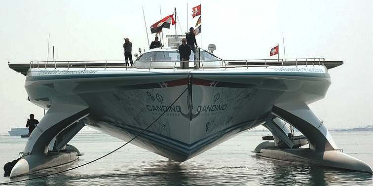
On the 4th of May 2012 the theory was proven to be correct by Raphael Domjan and his superb boat the Turanor Planetsolar, thanks to generous sponsorship by Candido Swiss watches and Immosolar, leaders in the field of solar energy management.
Now the benchmark has been set, it will undoubtedly inspire others. As with so many things once a pioneer has shown the way, inevitably, the record stands like mountain to be scaled.
March 2012 the PlanetSolar in the Suez Canal
|
||
|
This website is copyright © 1991- 2021 Electrick Publications. All rights reserved. The bird logo and names Solar Navigator and Blueplanet Ecostar are trademarks ™. The Blueplanet vehicle configuration is registered ®. All other trademarks hereby acknowledged and please note that this project should not be confused with the Australian: 'World Solar Challenge'™which is a superb road vehicle endurance race from Darwin to Adelaide. Max Energy Limited is an educational charity.
|